Chapter 2 Specifications and System Configuration
2-70
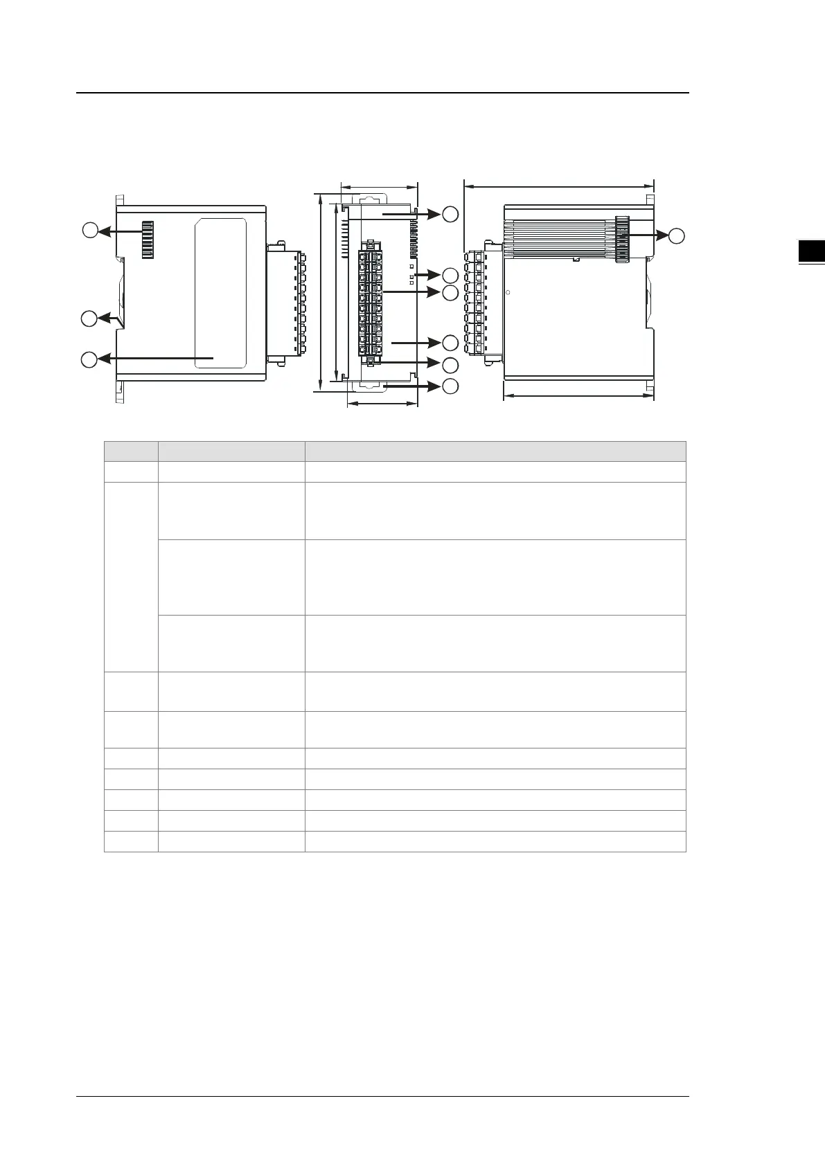
2.9.2 Load Cell Module Profiles
AS02LC-A
38.2
35
88
98.3
1
4
5
2
3
6
7
8
9
95
75
7
Unit: mm
2
POWER LED indicator
Indicates the status of the power supply
ON: the power is on
ERROR LED indicator
Error status of the module
ON: a serious error occurs in the module.
OFF: the module is normal.
Blinking: a minor error occurs in the module.
Analog to digital
conversion indicator
Indicates the analog to digital conversion status
Blinking: conversion is taking place
3
Removable terminal
block
The inputs are connected to sensors.
The outputs are connected to loads to be driven.
4
Arrangement of the
Arrangement of the terminals
Removal of the terminal block
6 DIN rail clip Secures the module onto the DIN rail
7 Module connecting set Connects the modules
 Loading...