Chapter 10 CANopen Function and Operation
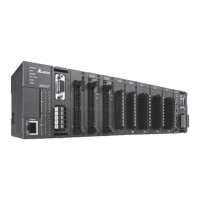
4. When finished, click the Download button on the toolbar to download the settings to the PLC.
10.2.4 The CAN Interface and Network Topology
10.2.4.1 Definitions of the CAN Signal and Data Types
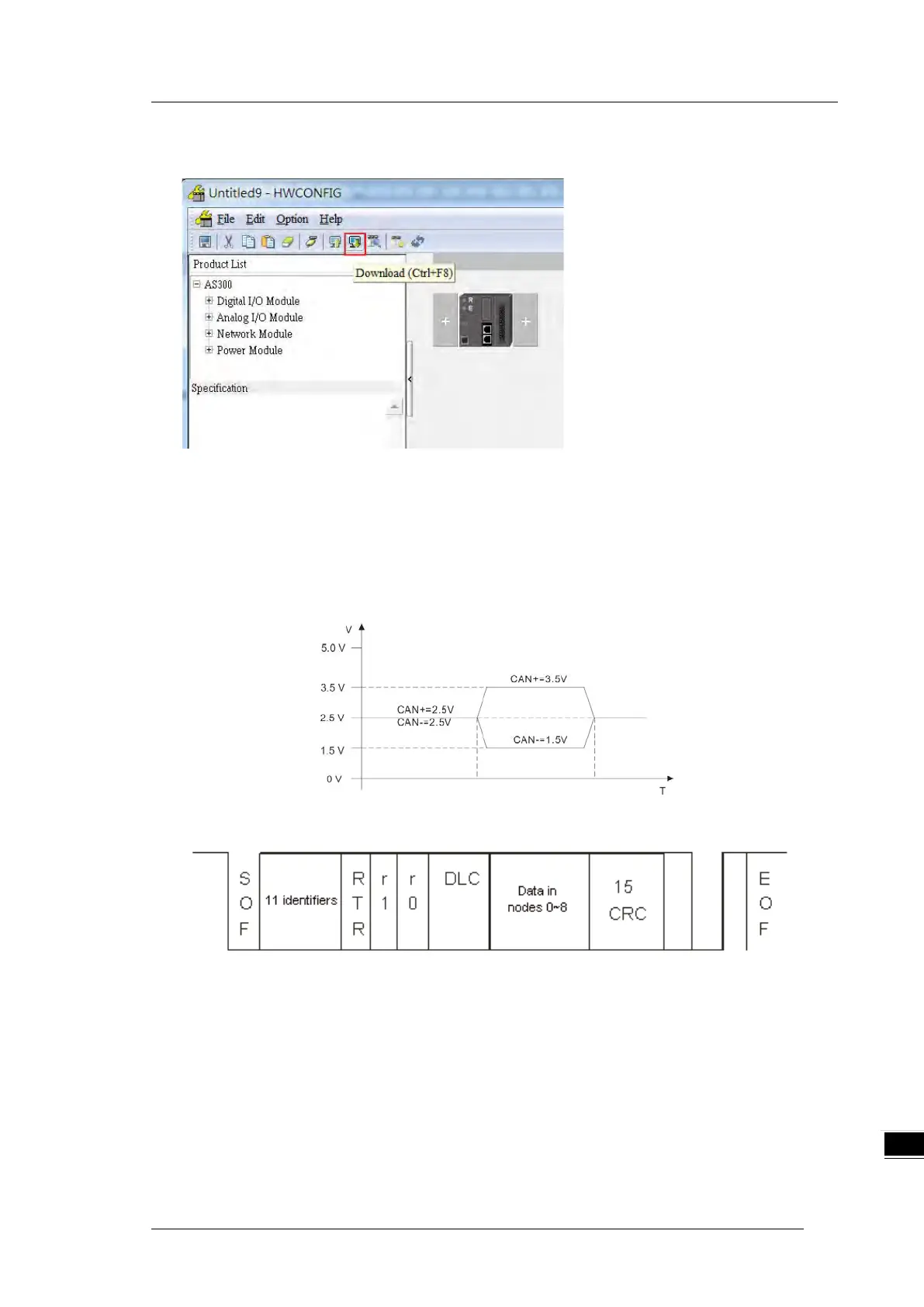
The CAN signal is a differential signal. The voltage of the signal is the voltage difference between CAN+ and
CAN-. The CAN+ and CAN- voltages take SG as a reference point. The CAN network can be in one of two
states. One state is a dominant level, and is indicated by the logical “0”. The other state is a recessive level,
and is indicated by the logical “1”. The CAN signal level shows below.
The following picture shows the data frame format. The CAN nodes transmit the CAN messages to the
network from left to right.
 Loading...