EasyManua.ls Logo

Delta AS16AP11P-A User Manual

Delta AS16AP11P-A
460 pages
To Next Page IconTo Next Page
To Previous Page IconTo Previous Page
Page #274 background imageLoading...
Page #274 background image
AS Series Operation Manual
9-66
_9
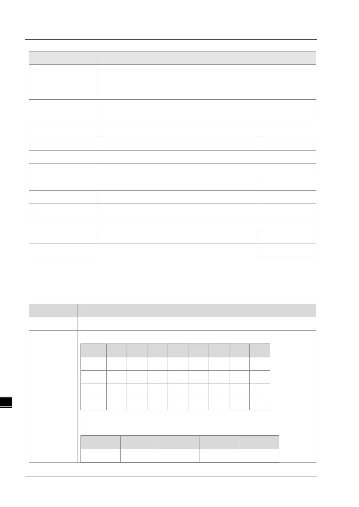
Object Name Function Class ID
TCP/IP Interface Object
Provides the mechanism to configure a devices TCP/IP
network interface; examples of configurable items include the
devices IP Address, Network Mask, and Gateway Address.
245 (HF5)
Ethernet Link Object
Maintains link-specific counters and status information for an
IEEE 802.3 communications interface.
246 (HF6)
X Register Bit/Word Register
848H’350
Y Register Bit/Word Register
849H’351
D Register Bit/Word Register
850H’352
M Register Bit Register
851H’353
S Register Bit Register
852H’354
T Register Bit/Word Register
853H’355
C Register Bit/Word Register
854H’356
HC Register Bit/Word Register
855H’357
SM Register Bit Register
856H’358
SR Register Word Register
857H’359
9.8.2 Data Type
This section provides an overview of the data types supported by objects.
Data Type Description
BOOL False(H’00) or True(H’01)
SIGNED
INTEGER
SINT(1 byte), INT(2 bytes), DINT(4 bytes), LINT(8 bytes)
Number 1st 2nd 3rd 4th 5th 6th 7th 8th
SINT 0LSB
INT 0LSB 1LSB
DINT 0LSB 1LSB 2LSB 3LSB
LINT 0LSB 1LSB 2LSB 3LSB 4LSB 5LSB 6LSB 7LSB
Example: DINT value = H’12345678
Number 1st 2nd 3rd 4th
DINT 78 56 34 12

Table of Contents

Question and Answer IconNeed help?

Do you have a question about the Delta AS16AP11P-A and is the answer not in the manual?

Delta AS16AP11P-A Specifications

General IconGeneral
ModelAS16AP11P-A
SeriesAS
Points16
Digital Inputs8
Digital Outputs8
Power Supply24 VDC
Input Voltage24 VDC
ProtectionIP20
Safety StandardsCE, UL
Operating Temperature55°C
Storage Temperature70°C

Summary

Chapter 2 Specifications and System Configuration

2.2 CPU Module Specifications

Details the functional and electrical specifications for various AS Series CPU modules.

2.3 Digital Input/Output Module Specifications

Covers general specifications, profiles, and terminals for digital input/output modules.

2.4 Analog Input/Output Module Specifications

Details specifications for analog input/output modules, including general specs, profiles, terminals, and device settings.

2.5 Temperature Measurement Modules Specifications

Details specifications for temperature measurement modules, including general specs, profiles, dimensions, and device settings.

2.6 Positioning Module Specifications

Covers specifications for positioning modules, including general specs, profiles, terminals, and device settings.

2.7 Counter Module Specifications

Covers specifications for counter modules, including general specs, profiles, terminals, and device settings.

2.8 Network Module Specifications

Covers specifications for network modules, including general specs, profiles, and device settings.

2.9 Load Cell Module Specifications

Covers specifications for load cell modules, including general specs and profiles.

2.10 Extension Card Specifications

Covers specifications for extension cards, including general specs and profiles.

2.11 Power Supply Module Specifications

Covers specifications for power supply modules, including general specs and profiles.

Chapter 3 Installing Software

3.1 Installing and Uninstalling ISPSoft

Provides step-by-step instructions for installing and uninstalling the ISPSoft software.

3.2 Installing and Uninstalling COMMGR

Details the procedures for installing and uninstalling the COMMGR communication manager software.

Chapter 4 Installing Hardware

Chapter 6 Writing a Program

6.6 Testing and Debugging a Program

Covers steps for testing and debugging a program by establishing a connection and monitoring the PLC online.

Chapter 7 Memory Card

7.6 Backing Up a Project

Guides on backing up projects to an AS Series CPU module or memory card, detailing LED indicators and SM flags.

7.7 Restoring a Project

Explains the process of restoring projects from an AS Series CPU module or memory card, including LED indicators.

7.8 Restoration Starts Once CPU is supplied with Power

Describes how the CPU module performs restoration automatically when power is supplied if the backup file is consistent.

7.9 CPU Error Log

Explains how the system stores CPU error messages on the memory card and how to read them using special flags SM36 and SR36.

Chapter 8 Hardware Configuration and Data Exchange Setups

8.1 Hardware Configuration Tool for AS Series Modules - HWCONFIG

Introduces the HWCONFIG tool for AS Series modules and its environment.

Chapter 9 EtherNet/IP

Chapter 10 CANopen Function and Operation

Chapter 11 CPU Module Operating Principles

Chapter 12 Troubleshooting

12.2 Troubleshooting for CPU Modules

Details error codes and LED indicators for CPU modules, categorizing errors by LED status and blinking patterns.

12.3 Troubleshooting for I/O Modules

Covers troubleshooting for various I/O modules, including analog, temperature, positioning, counter, load cell, and network modules.

12.4 Error Codes and LED Indicators for CPU Modules

Provides a comprehensive list of error codes and their corresponding LED indicator status and CPU states for CPU modules.

Chapter 13 Data Tracer and Data Logger

Appendix A Installing a USB Driver

Related product manuals