Chapter 2 Specifications and System Configuration
2-64
2.8.2 Network Module Profiles
AS00SCM-A
1
4
5
2
6
75
98 .3
88
56
3
7
8
9
7
10
SCM
PO WER
CA RD 1
CA RD 2
ER RO R
F OR MA T 2
C OM . RTU
ID 2
FOR MAT 1
ID 1
Unit: mm
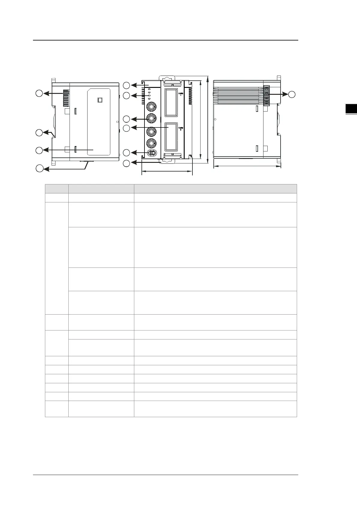
1 Model name Model name of the module
2
POWER LED indicator
Indicates the status of the power supply
ON: the power is on
OFF: no power or the power is low
ERROR LED indicator
Error status of the module
OFF: The module is normal.
Blinking:
Module setting or communication error (blinks every 1 second)
Hardware or low power error (blinks every 0.2 second)
Extension card 1
indicator
Blinking: communication is taking place in card 1
OFF: No communication in card 1
Extension card 2
indicator
Blinking: communication is taking place in card 2
OFF: No communication in card 2
3
Address and function
2 sets for setting up the address and function in card 1 and 2
4
Available for AS-F232/AS-F422/AS-F485/AS-FEN02
Slot for function card 2
Available for AS-F232/AS-F422/AS-F485/AS-FCOPM
AS-FEN02 (only for RTU mode)
COM: communication mode ; RTU: remote control mode
Secures the module onto the DIN rail
10
Input for supplying power
to remote modules
Power supply for the remote module
 Loading...