DVP-ES3 Series Operation Manual
4-36
*3. If noise in the input voltage results in noise interference in the wiring, connect the module to a capacitor with
a capacitance between 0.1–0.47 μF with a working voltage of 25 V.
*4. Connect FE of the shielded cable to ground.
*5. Connect the terminal to ground.
*6. Every channel can work with the wiring shown above.
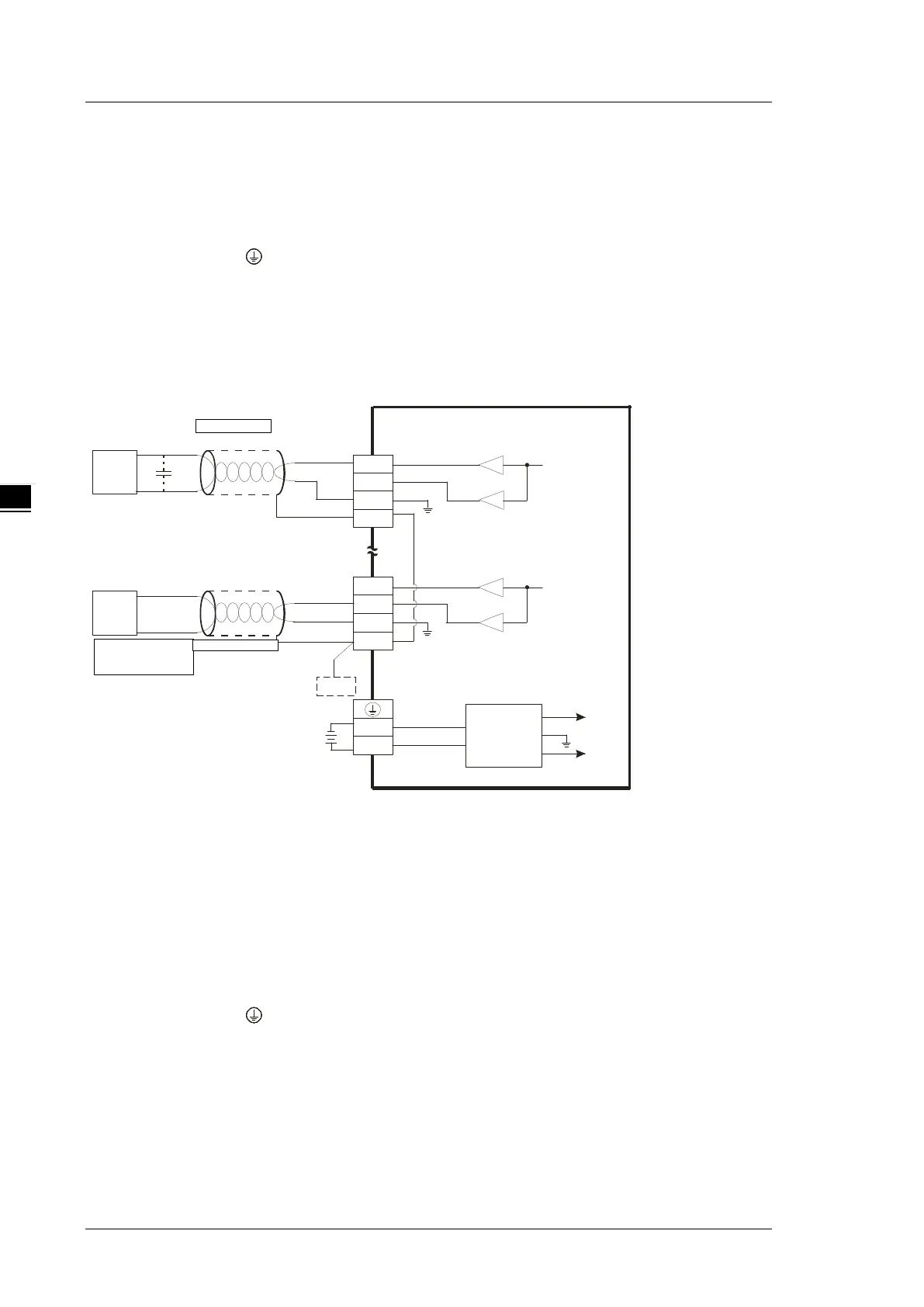
4.8.2 Wiring DVP02DA-E2/DVP04DA-E2
Converter
VO4
IO4
AG
CHX
0mA~20mA
CH4
AG
VO1
IO1
AG
CHX
-10V~+10V
*2
CH1
AG
24VDC
DC/DC
+15V
-15V
AG
FE
FE
FE
*3
0V
24V
*4
*4
AC motor drive,
recorder,
proportioning valve
AC motor drive,
recorder,
proportioning valve
*1. Use shielded cables to isolate the analog input signal cable from other power cables.
*2. If noise in the input voltage results in noise interference in the wiring, connect the module to a capacitor with
a capacitance between 0.1–0.47 μF with a working voltage of 25 V.
*3. Connect the terminal to ground.
*4. Every channel can work with the wiring shown above.

 Loading...


