Chapter 5 CPU and Module Devices
5-3
number F500, enter 500.0 in ISPSoft.
*3: Strings are indicated by $ in Chapter 5 and Chapter 6 in the DVP-ES3 Series Programming Manual, but they are
represented by quotes (“ ”) in ISPSoft. For example, for the string of 1234, enter “1234” in ISPSoft.
*4: Used for editing in ISPSoft only.
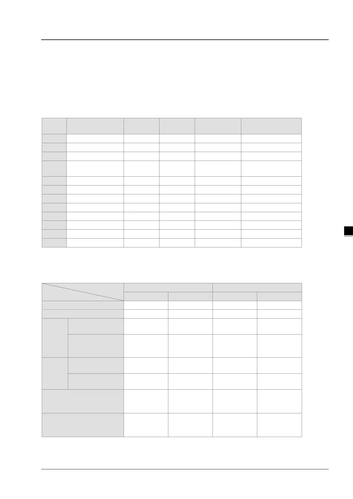
5.1.2 Basic Structure of I/O Storage
Device Function
Access by
Access by
Modify by
Force the bit ON/OFF
Input relay OK OK OK OK
SM
Special auxiliary
OK - OK -
Special data register - OK OK -
1
*1: Use an instruction for writing to an FR.
5.1.3 Relation Between the PLC Action and the Device Type
Device type
PLC action
STOP
↓
RUN*
1
The non-latched
Cleared Cleared Retained Retained
The state of the
non-latched area is
Retained Retained Retained Retained
RUN
↓
STOP*
1
The state of device
Cleared Retained Retained Retained
The state of device
Retained Retained Retained Retained
SM204 is ON.
(All non-latched areas are
Cleared Cleared Retained Retained
SM205 is ON.
(All latched areas are
Retained Retained Retained Cleared
*1: For more on setting the states, see HWCONFIG in ISPSoft. The default for PLC STOP->RUN is “clear not-latched
area”. The default for PLC RUN->STOP is “clear the state of device Y”.

 Loading...


