Chapter 5 CPU and Module Devices
5-19
5.3. Module Device Functions
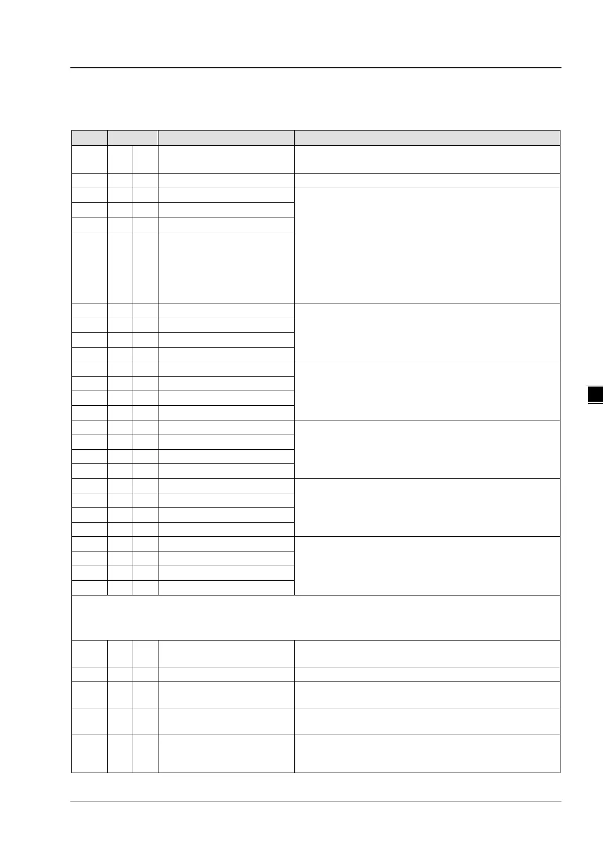
5.3.1 DVP04AD-E2 Control Registers
0 O R Model name
Set up by the system:
DVP04AD-E2 model code = H’0080
Display the current firmware version in hex. format
2 O R/W CH1 input mode setting
Input mode: Default = H’0000.
Mode 0 (H’0000): Voltage input (±10V)
Mode 1 (H’0001): Voltage input (±5V)
Mode 2 (H’0002): Voltage input (0 ~ +10V)
Mode 3 (H’0003): Voltage input (0 ~ +5V)
Mode 4 (H’0004): Current input (±20mA)
Mode 5 (H’0005): Current input (0 ~ +20mA)
Mode 6 (H’0006): Current input (+4~ +20mA)
Mode -1 (H’FFFF): Channel 1 unavailable
5 O R/W CH4 input mode setting
Set sampling range in CH1 ~ CH4:
Range = K1 ~ K100
Default = K10
Average value of input signals at CH1 ~ CH4
Present value of input signals at CH1 ~ CH4
Adjusted Offset value of CH1
Set the adjusted Offset value of CH1 ~ CH4. Default = K0
Adjusted Offset value of CH2
Adjusted Offset value of CH3
Adjusted Offset value of CH4
Adjusted Gain value of CH1
Set the adjusted Gain value in CH1 ~ CH4. Default = K16,000
Adjusted Gain value of CH2
Adjusted Gain value of CH3
Adjusted Gain value of CH4
Adjusted Offset Value, Adjusted Gain Value:
Note1: When using Mode 6 for input, the channel do NOT provide setups for adjusted Offset or Gain value.
Note2: When input mode changes, the adjusted Offset or Gain value automatically returns to defaults.
40 O R/W
Function: Set value changing
Prohibit set value changing in CH1 ~ CH4. Default= H’0000.
Function: Save all the set values
Save all the set values, Default =H’0000
43 X R Error status
Register for storing all error status. Refer to table of error status
100 O R/W
Function: Enable/Disable limit
Upper and lower bound detection, b0~b3 corresponds to
Ch1~Ch4 (0: Enable/1: Disable). Default= H’0000.
101 X R/W Upper and lower bound status
Display the upper and lower bound status (0: Not exceed /1:
Exceeds upper or lower bound value), b0~b3 corresponds to
Ch1~Ch4 for lower bound detection result; b8~b11 corresponds

 Loading...


