DVP-ES3 Series Operation Manual
4-40
*4. Connect FE of the shielded cable to ground when the noise it too loud.
*5. Connect the terminal to ground.
*6. CHX: Every channel can work with the input wiring shown above.
Note 1: use cables with the same length (less than 200 m) and use terminal resistors of less than 200 ohm.
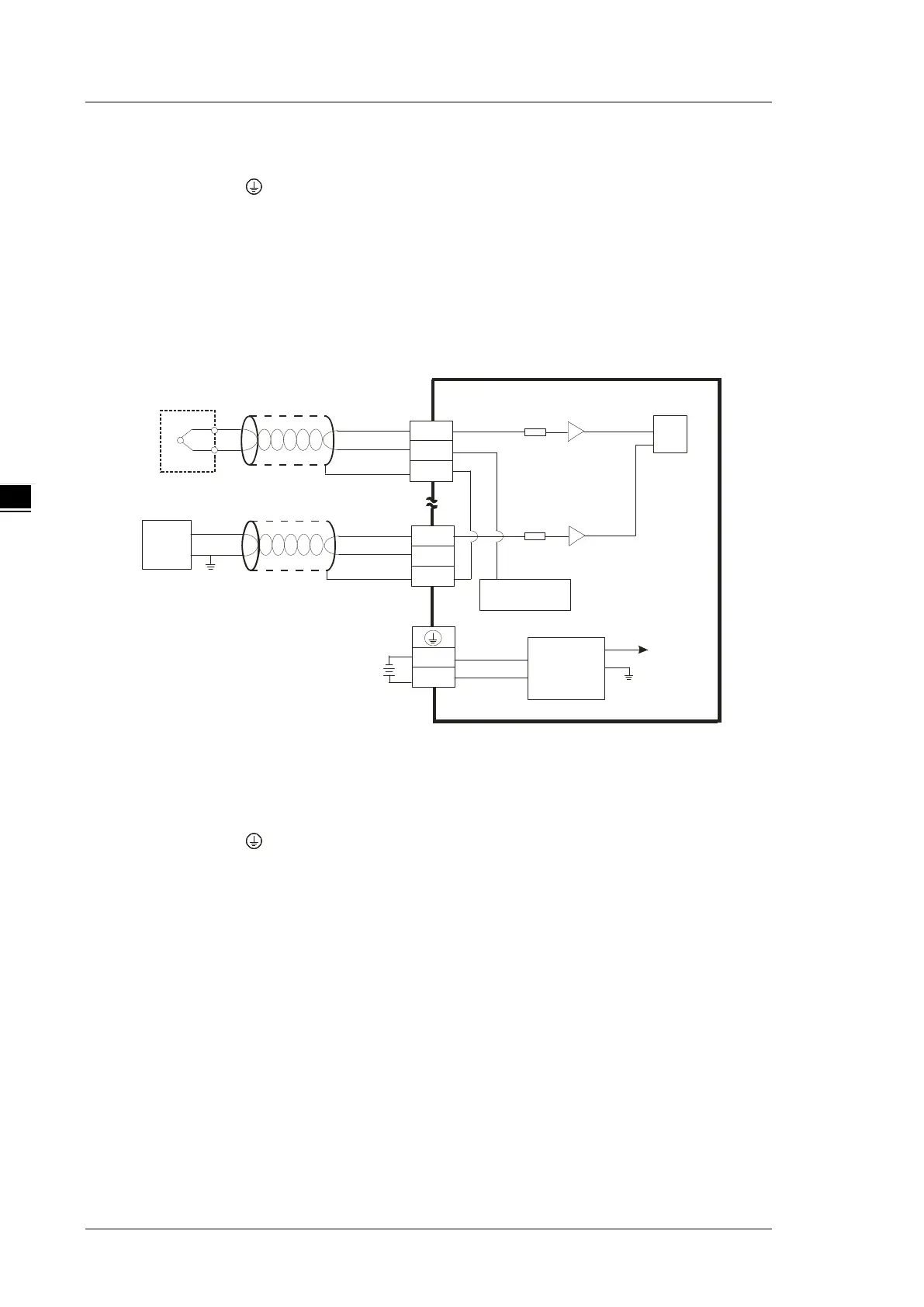
4.9.2 Wiring DVP04TC-E2
+
-
I4+
I4-
Cold conjunction
compensation
MUX
+
-
J,K,R,S,T,E,N
-80mV~80mV
I1+
I1-
FE
FE
Shielded cable*1
24VDC
DC/DC
Converter
5V
AG
0V
24V
*2
CHX
*3
CHX
*3
Shielded cable*1
*1. The cable connected to the input terminal should be the cable or the shielded twisted pair cable connected
to a type J, K, R, S, T, E, N thermocouple. It should be kept separate from other power cables and cables
that generate noise.
*2. Connect the terminal to ground.
*3. CHX: Every channel can work with the input wiring shown above.
Note 1: only use copper conducting wires with a temperature rating of 60/75°C and the length must be less
than 50 m.
Note2: TC modules must run for 30 minutes before they start to take any temperature measurement.

 Loading...


