Chapter 2 Specifications and System Configuration
2-6
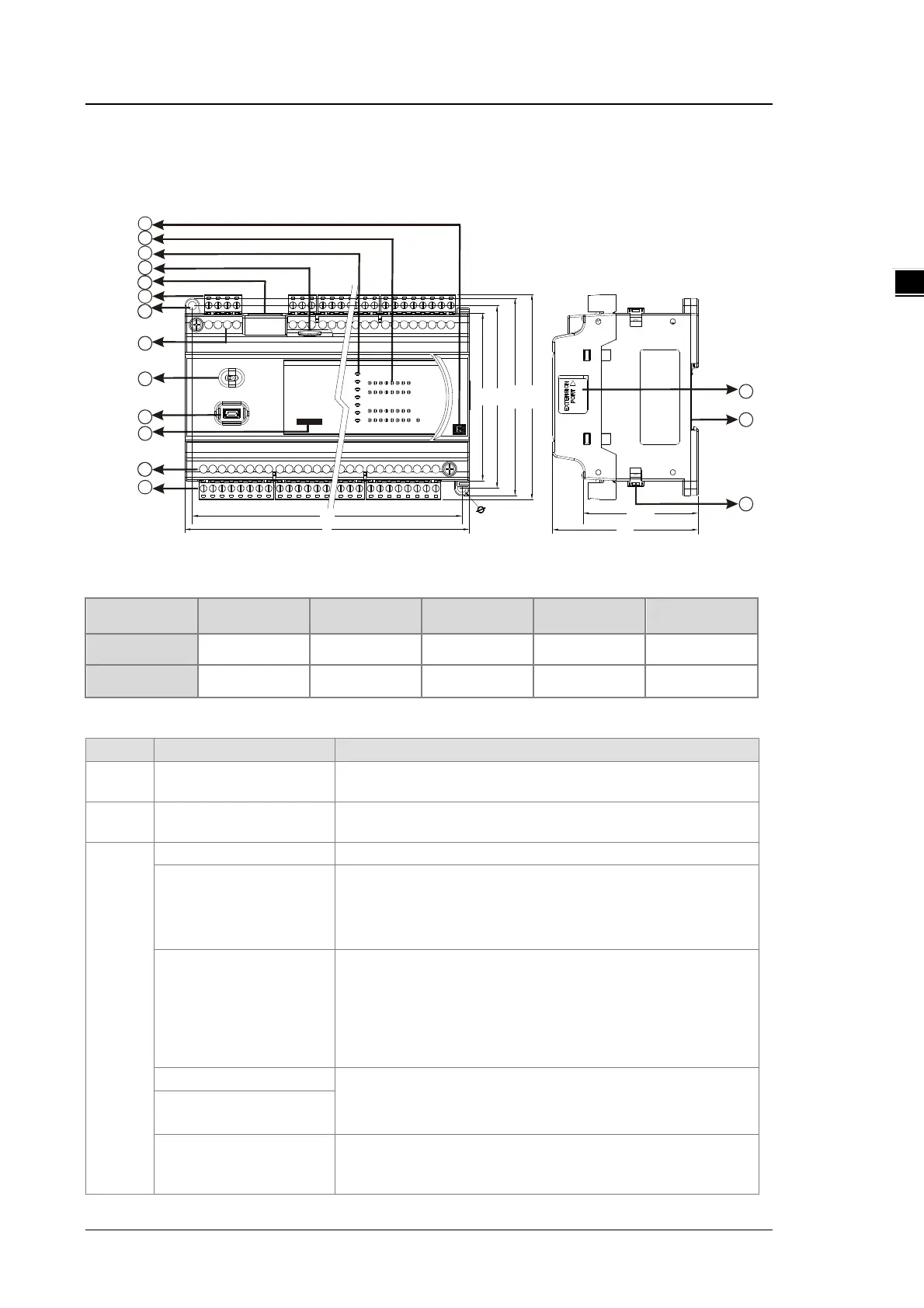
2.2.3 CPU Module Profiles
DVP32ES300R / DVP32ES300T / DVP32ES311T / DVP48ES300R / DVP48ES300T / DVP64ES300R /
DVP64ES300T / DVP80ES300R / DVP80ES300T
L1
L
90
98
106
110
61.5
78
4
.
5
x
2
7
8
1
4
5
3
6
2
DV P32 ES3
16DI / 1 6DO
8
6
9
10
14
12
13
11
Unit: mm
Diameter chart
DVP 32ES311T 32ES300R/T 48ES300R/T 64ES300R/T 80ES300R/T
L
165 mm 165 mm 216 mm 267 mm 310 mm
L1
157 mm 157 mm 208 mm 259 mm 302 mm
LED indocaor descriptions
1 Output type
R: Relay output
2 Input/Output LED
If there is an input signal, the input LED indicator is ON.
If there is an output signal, the output LED indicator is ON.
3
Indicates the power status of the CPU module
Run LED
Operating status of the module
ON: the program is running.
OFF: the program is stopped.
Blinking: the program detects an error
Error LED
Error status of the module
Blinking slowly (1 second ON, 3 seconds OFF): warning
Blinking (0.5 seconds ON, 0.5 seconds OFF): error occurs
Blinking rapidly (0.2 seconds ON, 0.2 seconds OFF)
ON: scanning timeout
OFF: the module is normal.
Indicates the communication status
OFF: no communication
Blinking: communication
COM1 LED
LINK/ACT LED
ON: communication port is connected
Blinking: packet sending/receiving
OFF: communication port is not connected

 Loading...


