DVP-ES3 Series Operation Manual
10.6 Application Example
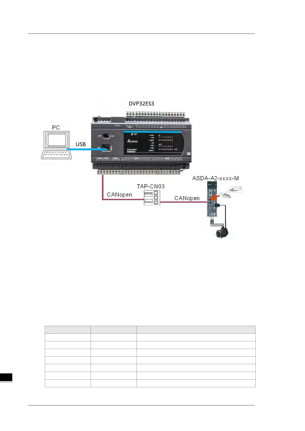
The DVP-ES3 Series PLC can control Delta A2 servo rotation, and monitor the actual rotation speed of the
motor in real time. It does this by mapping the relevant servo drive parameters to the corresponding PDO, and
reads or writes the relevant servo drive parameters through the CAN bus.
1. Connectting the Hardware
Note:
Use a standard communication cable such as UC-DN01Z-01A / UC-DN01Z-02A / UC-CMC010-01A
and connect the terminal resistors (Delta standard terminal resistor TAP-TR01) to both ends of the
network when you construct the network.
M of ASD-A2-xxxx-M refers to the model code and currently only the M-model servo supports
CANopen communication.
2. Setting Servo Parameters:
Set servo parameters as shown in the following table.
Node ID of the A2 servo is 2
CAN communication rate is 1Mbps.
1-01 04 Speed mode
0-17 07 Drive displays the motor rotation speed (r/min)
Set DI1 as the signal for Servo On
Set DI3 as the signal _SPD0 for speed selection
Set DI4 as the signal _SPD1 for speed selection

 Loading...


