EasyManua.ls Logo

Delta DVP-ES3 Series User Manual

Delta DVP-ES3 Series
411 pages
To Next Page IconTo Next Page
To Previous Page IconTo Previous Page
Page #185 background imageLoading...
Page #185 background image
Chapter 6 Writing a Program
6-35
6_
The following describes the columns in the monitoring table.
Column Description
Source Source of a symbol
Identifier Identifier of a symbol
Device name Name of a monitored device
Status State of a monitored bit device or a contact (ON or OFF).
Data type Data type of a monitored symbol.
Value (16 bits) In online mode, displays a 16-bit value.
Value (32 bits) In online mode, displays a 32-bit value.
Float In online mode, displays a 32-bit floating-point number.
Radix Select a format to represent a value.
Comment Display the comments on a device or on a symbol.
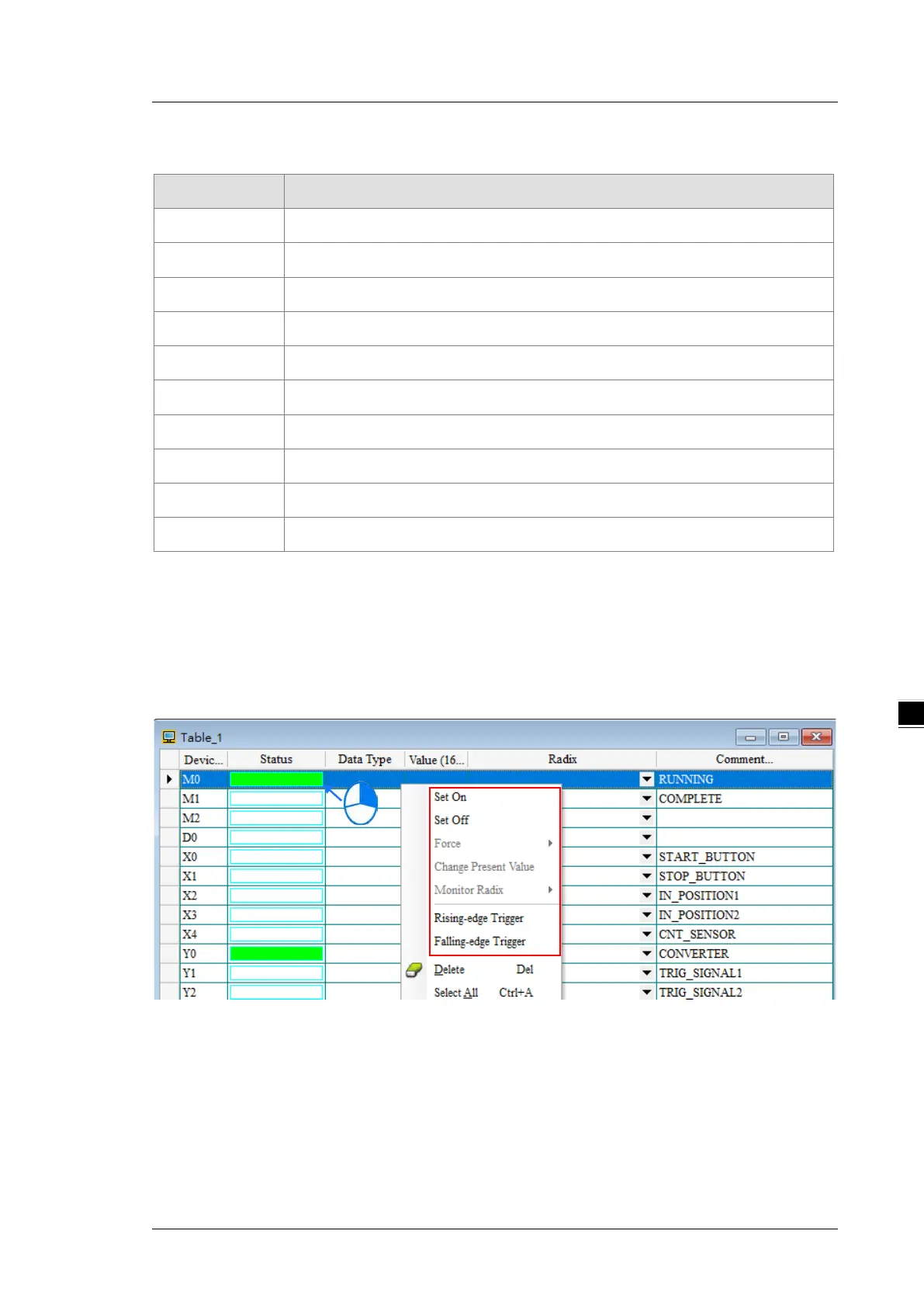
After you create the monitoring table, you can monitor the items in the monitoring table in online mode.
Right-click an item in the monitoring table in online mode to display a context menu which is the same as the
context menu in the program editing window. You can change the item state or the item value by clicking an
item in this context menu.
You can text and debug the program you created in this chapter through the monitoring table you created in this
section. Refer to Chapter 17 in the ISPSoft User Manual for more information about testing and debugging a
program.

Table of Contents

Other manuals for Delta DVP-ES3 Series

Question and Answer IconNeed help?

Do you have a question about the Delta DVP-ES3 Series and is the answer not in the manual?

Delta DVP-ES3 Series Specifications

General IconGeneral
SeriesDVP-ES3 Series
CategoryController
Program CapacityUp to 32K steps
Input Voltage24V DC
Power SupplyAC or DC (depending on model)
I/O PointsUp to 256 points
Digital InputsUp to 128 points
Digital OutputsUp to 128 points
Communication PortsRS-232, RS-485
Programming LanguageLadder Diagram
Operating Temperature0°C to 55°C
Storage Temperature-20°C to 70°C
Humidity5% to 95% RH, non-condensing
Pulse Output2 points 10kHz / 2 points 20kHz (depending on model)

Summary

Chapter 1 Product Introduction

1.1 Overview

Provides an overview of the DVP-ES3 Series PLC's functions, devices, and troubleshooting.

1.3 Characteristics

Details high efficiency, I/O support, program capacity, and IEC 61131-3 compliance of the CPU module.

Chapter 2 Specifications and System Configuration

2.2 CPU Module Specifications

Outlines functional and electrical specifications, programming languages, and instruction execution speed.

2.3 Digital Input/Output Module Specifications

Covers general specs, profiles, and electrical specifications for digital I/O modules.

2.4 Analog Input/Output Module Specifications

Details general specs, profiles, and electrical specifications for analog I/O modules.

Chapter 3 Installing Software

3.1 Installing and Uninstalling ISPSoft

Guides through installing and uninstalling ISPSoft software, including system requirements.

3.2 Installing and Uninstalling COMMGR

Explains the process of installing and uninstalling COMMGR software.

Chapter 4 Installing Hardware

4.1 DVP-ES3 Hardware Framework

Introduces hardware components, system limits, necessary, and optional components for DVP-ES3 PLC.

4.3 Installation

Provides instructions for installing the PLC and modules in a control box or on a DIN rail.

4.4 Wiring

Covers general warnings and notes for wiring I/O modules, including cable specifications.

4.5 Connecting Power Cables

Details precautions for connecting AC and DC power cables, including grounding methods.

Chapter 5 CPU and Module Devices

5.1 Introduction to CPU Devices

Explains device naming conventions, I/O storage structure, and PLC actions related to device types.

5.2 CPU Device Functions

Details functions of CPU devices like values, constants, floating-point numbers, relays, timers, and counters.

Chapter 6 Writing a Program

6.2 Procedure for Creating a Project in ISPSoft

Outlines steps for project creation, including hardware, network, programming, and testing phases.

6.5 Creating a Program

Details program creation, including adding ladder diagrams, basic editing, and instructions.

6.6 Testing and Debugging a Program

Covers creating connections, downloading programs, and performing connection and monitoring tests.

Chapter 7 Memory Cards

7.1 Overview of Memory Cards

Introduces MicroSD cards supported by DVP-ES3 Series and their specifications.

7.6 Backing Up a Project

Guides on backing up projects, including program code, parameters, and hardware configuration.

7.7 Restoring a Project

Explains how to restore projects from backup files to the CPU module or PC.

Chapter 8 Hardware Configuration and Data Exchange Setups

8.1 Hardware Configuration Tool for DVP-ES3 Series Modules - HWCONFIG

Introduces HWCONFIG for setting CPU/module parameters, downloading, and diagnostics.

8.2 Setting the Parameters in a DVP-ES3 Series CPU Module

Details how to set CPU parameters, including System Information and System Parameter.

8.3 Data Exchange

Explains setting up data exchange tables for COM ports and Ethernet communication.

Chapter 9 EtherNet/IP Specification and Operation

9.2 Installation

Covers installing EtherNet/IP devices, network cable setup, and EIP Builder software.

9.3 Specifications

Lists Ethernet and EtherNet/IP specifications, including communication protocols, speed, and ports.

9.5 Troubleshooting

Provides an overview of error codes and troubleshooting for EtherNet/IP configuration and application errors.

9.6 Studio 5000 Software Operation

Explains using Rockwell Automation's Studio 5000 for connecting to Delta Ethernet/IP Adapters.

Chapter 10 CANopen Function and Operation

10.1 Introduction to CANopen

Introduces CANopen networks, benefits, and supported functions like PDO, SDO, and NMT services.

10.3 The CANopen Protocol

Explains the CANopen protocol, OSI model, object dictionary, and communication objects.

10.5 Troubleshooting

Provides troubleshooting steps for CANopen network node states and error codes.

Chapter 11 CPU Module Operating Principles

11.1 CPU Module Operations

Describes the CPU module's operation upon power supply, diagnosis, and program execution.

11.2 CPU Module Operating Modes

Explains the STOP and RUN modes and their corresponding status and operations.

Chapter 12 Troubleshooting

12.1 Troubleshooting

Provides basic troubleshooting steps, error clearing methods, SOP, and system log access.

12.2 Troubleshooting for CPU Modules

Addresses errors indicated by ERROR LED status and provides corresponding solutions.

12.4 LED Indicators and Error Codes for CPU Modules

Presents a table of CPU module LED indicators, error codes, and their descriptions.

Chapter 13 Data Tracer and Data Logger

13.1 Data Tracer

Explains using Data Tracer for real-time data collection and curve charting for trend analysis.

13.2 Data Logger

Describes using Data Logger for long-term recording of variables and values for trend analysis.

Appendix A Installing a USB Driver

A.1 Disable Driver Signature Enforcement

Guides on disabling driver signature enforcement in Windows 8 and 10 for driver installation.

A.2 Installing the USB Driver for DVP-ES3 Series CPU Module

Explains the steps to install the USB driver for the DVP-ES3 Series CPU module on Windows 10.

Appendix B Device Addresses

B.1 Standard Modbus Device Addresses

Lists standard Modbus device addresses for various register types (X, Y, M, SM, S, T, C, HC, D, SR, E).

Appendix C EMC Standards

C.1 EMC Standards for an AS Series System

Lists EMC standards applicable to DVP-ES3 Series systems, covering EMI and EMS.

C1.2 Installation Instructions to meet EMC Standards

Provides instructions for installing the PLC in a control box and connecting power/ground for EMC compliance.

Appendix D Maintenance and Inspection

D.1 Cautions

Lists essential precautions before performing maintenance and inspection to prevent damage or injury.

D.2 Daily Maintenance

Outlines daily inspection steps for the PLC system, including appearance, installation, and connection checks.

D.3 Periodic Maintenance

Describes periodic maintenance based on operating environment and inspection items like ambient conditions and supply voltage.

Related product manuals