Patient Monitor User Manual Monitoring ECG
- 90 -
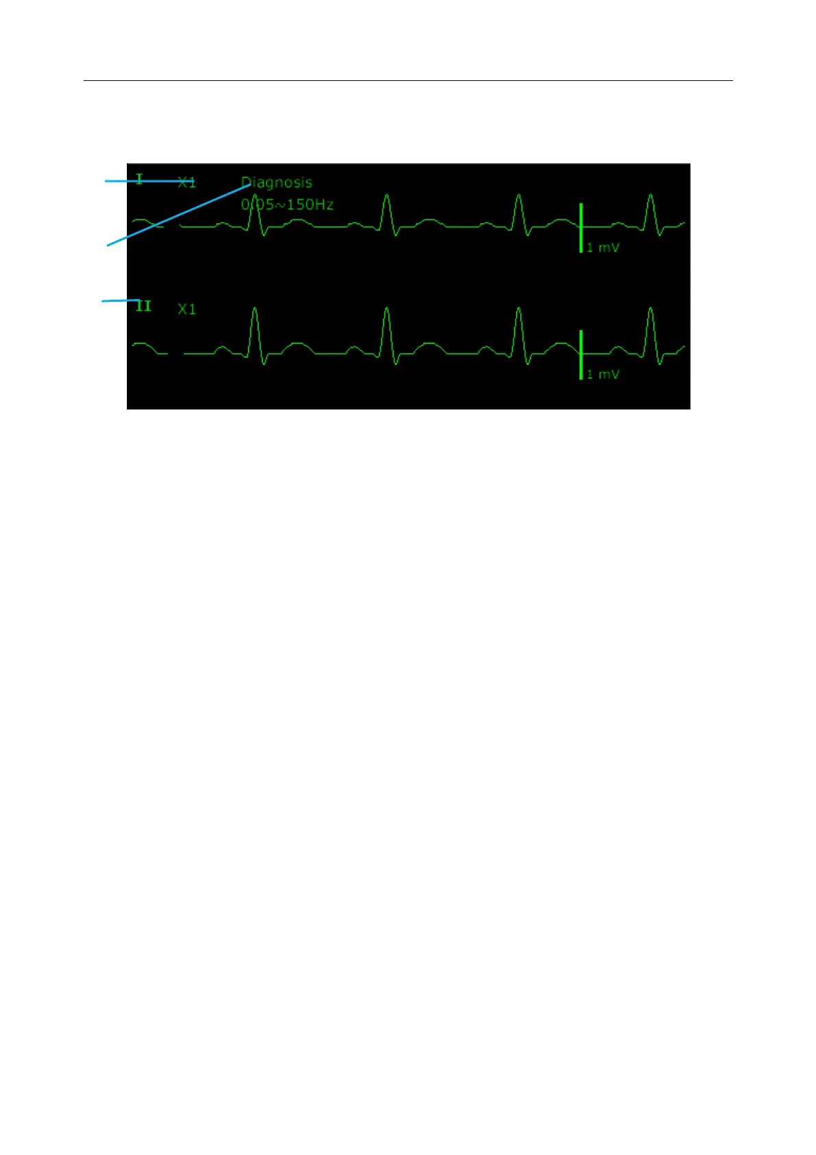
9.3 ECG Display
The figure below is for reference only.
The symbol “①”indicates lead name of display waveform: there are several options, such as I, II,
III, aVR, aVF, aVL, V (for 5 Electrodes). If you want to change the lead, please refer to section
Selecting Calculation Lead.
The symbol “②” indicates Filter setting, there are six options: Monitor, Surgery, Diagnosis,
Enhanced, Diagnosis 1, and Customized. If you want to change it, please refer to section
Changing the ECG Filter Setting.
The symbol “③” indicates waveform gain: there are several options, such as X0.125, X0.25,
X0.5, X1, X2, X4 and AUTO. If you want to change it, please refer to section Changing the Size
of the ECG Wave.
9.3.1 Changing the Size of the ECG Wave
If any of the displayed ECG waveform is too small or clipped, you can change the size of it on
the screen. First select ECG Waveform Setup > ECG Gain, then select an appropriate factor
from the pop-up box to adjust the ECG waveform.
X0.125: make the size of 1 mV ECG waveform signal become 1.25 mm;
X0.25: make the size of 1 mV ECG waveform signal become 2.5 mm;
X0.5: make the size of 1 mV ECG waveform signal become 5 mm;
X1: make the size of 1 mV ECG waveform signal become 10 mm;
X2: make the size of 1 mV ECG waveform signal become 20 mm;
X4: make the size of 1 mV ECG waveform signal become 40 mm;
AUTO let the monitor choose the optimal adjustment factor for all the ECG waves.
NOTE:
The effect of ECG wave gain is subject to the size of the wave area. Whichever wave
gain is chosen, the ECG wave has to be displayed within the wave area, the exceeded
part is clipped.
①
③
 Loading...