3.3 Wiring guidelines
This section contains general information and wiring hints. As always, proper cable
installation depends on observation and judgment based on the situation on-site. Observe
the following points for a reliable cable installation:
• Install cables according to general standards for measuring and control cables.
• Separate AC voltage circuits from low voltage signals to comply with safety
recommendations and to mitigate induced noise in the signals. This good practice is
recommended by Emerson although any signal type can be installed in any CHARM slot
of the AMS Asset Monitor.
• If possible, install cables in metallic cable channels or tubes.
• Observe an orthogonal cable routing.
• Do not squeeze, bent, or twist cables. Always observe the permissible bending radius
of the used cable.
• Install cables strain-free and spin-free to protect them against mechanical damages.
• Affix cables to a secure surface at regular, short distances.
• Ensure that no parts of the cable touch any rotating parts of the machine.
• Note that machine parts or other metallic parts can expand or shrink due to
temperature influences. Always install cables with a cable length reserve to
compensate the thermal behavior of such parts.
•
Always use ferrules for stranded wires. Ensure that all strands are covered by the
ferrule so that no strand can contact an adjacent terminal. When strands are
stripped 10 mm and ferrules are not used, consider that there is a risk of short
circuit – a possibility of accidental contact between HAZARDOUS LIVE parts of
different polarity.
• At environmental temperatures of 50°C and above use cables suitable for temperatures
above 60°C within the AMS Asset Monitor.
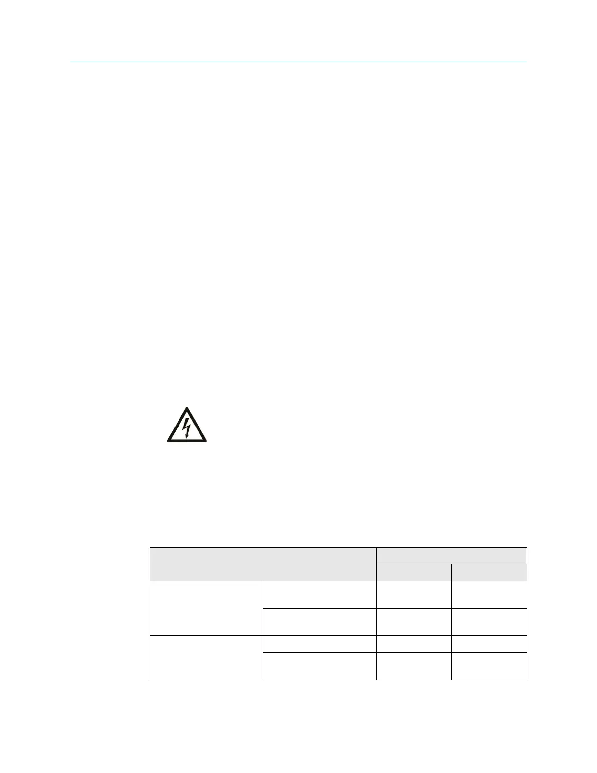
See Table 3-2 for the permissible wire-cross sections for the voltage supply terminals and
cable shield terminals. For the maximum tightening torque see Torque limits for mounting
screws.
Table 3-2: Permissible wire-cross sections
Wire description Wire cross-section
Minimum Maximum
Power supply terminals Conductor cross section
stranded
0.2 mm
2
2.5 mm
2
Conductor cross section
stranded AWG
24 12
Cable shield terminals Conductor cross section 0.32 mm
2
2.5 mm
2
Conductor cross section
AWG
22 14
Planning the installation Installation Guide
March 2024 MHM-97923-PBF
16 MHM-97923-PBF, Rev. 2.10

 Loading...


