5.1.1 Connect the power supply
Procedure
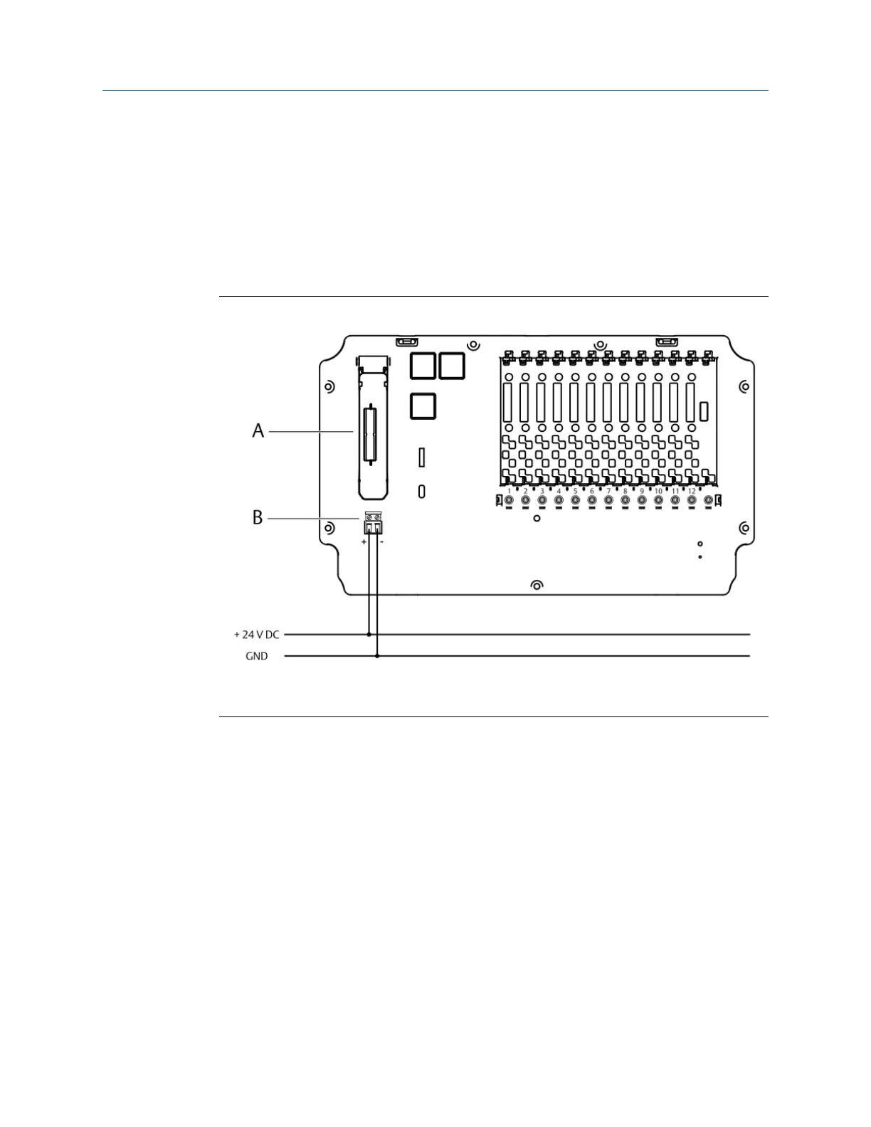
Connect a +24 V DC power supply to the power supply terminals of the AMS Asset
Monitor.
Connect the +24 V DC of the power supply to the + terminal of the AMS Asset Monitor and
GND of the power supply to the - terminal.
Figure 5-6: Power supply connection
A. Slot for the +24 V DC Power Module
B. Power supply terminals
5.2 Install a VI Piezo CHARM
The VI Piezo CHARM is designed for the connection of 2-wire piezoelectric sensors or 2-
wire IEPE strain sensors. The VI Piezo CHARM is supplied by the AMS Asset Monitor. A
CHARM Terminal Block is required for the installation. See installation guide of the VI Piezo
CHARM for further details. See Installing CHARMs hardware for the general CHARM
installation procedure.
Installing CHARMs hardware Installation Guide
March 2024 MHM-97923-PBF
46 MHM-97923-PBF, Rev. 2.10

 Loading...


