Procedure
1. At opened door, lead the sensor cable through a cable gland close to the slot where
the CHARM to be connected is installed.
2. Strip the cable sheath at a length of approximately 200 mm.
3. Strip each wire at a length of approximately 10 mm.
4. Connect the wires to the CHARM Terminal Block.
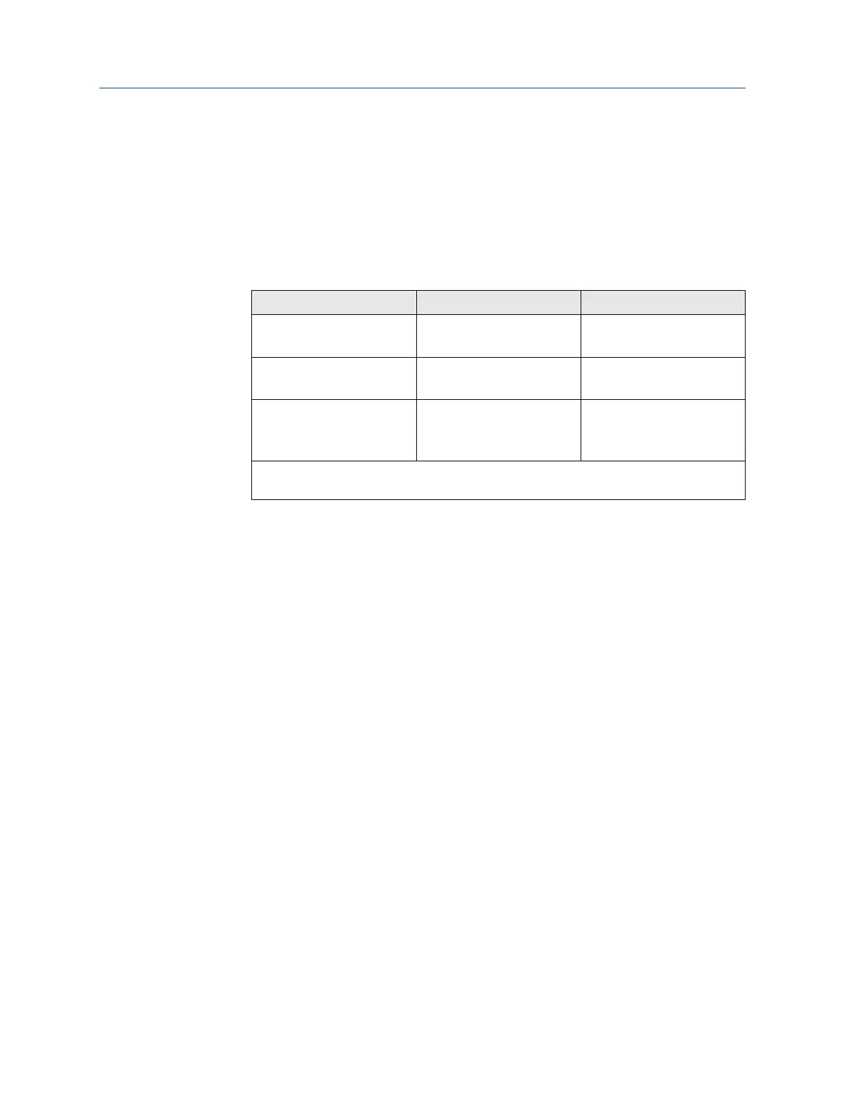
Table 5-1:
Sensor Sensor terminals CHARM terminals
Magnetic pickup Signal Out
Signal GND
1
2
Output signal of an eddy
current measuring chain
Out
GND
1
2
Hall-effect sensor Signal Out
GND
+24 V Power Supply
1
2
3
Connect the cable shield to a grounding terminal (see Grounding). With Hall-effect sensors,
only if the cable shield is not used for signal GND and supply GND.
5. Ensure that the cable gland, where the signal cable is led through, is closed to keep
the IP protection class of the AMS Asset Monitor.
6. Continue with the installation or close the door (see Close the AMS Asset Monitor).
5.4 Install a VI Voltage CHARM
The VI Voltage CHARM is designed for the connection of voltage signals in the range of -24
V to +24 V. The VI Voltage CHARM is supplied by the AMS Asset Monitor. A CHARM
Terminal Block is required for the installation. See installation guide of the VI Voltage
CHARM for further details. See Installing CHARMs hardware for the general CHARM
installation procedure.
Installing CHARMs hardware Installation Guide
March 2024 MHM-97923-PBF
52 MHM-97923-PBF, Rev. 2.10

 Loading...


