5.2.1 Connect the sensor wiring
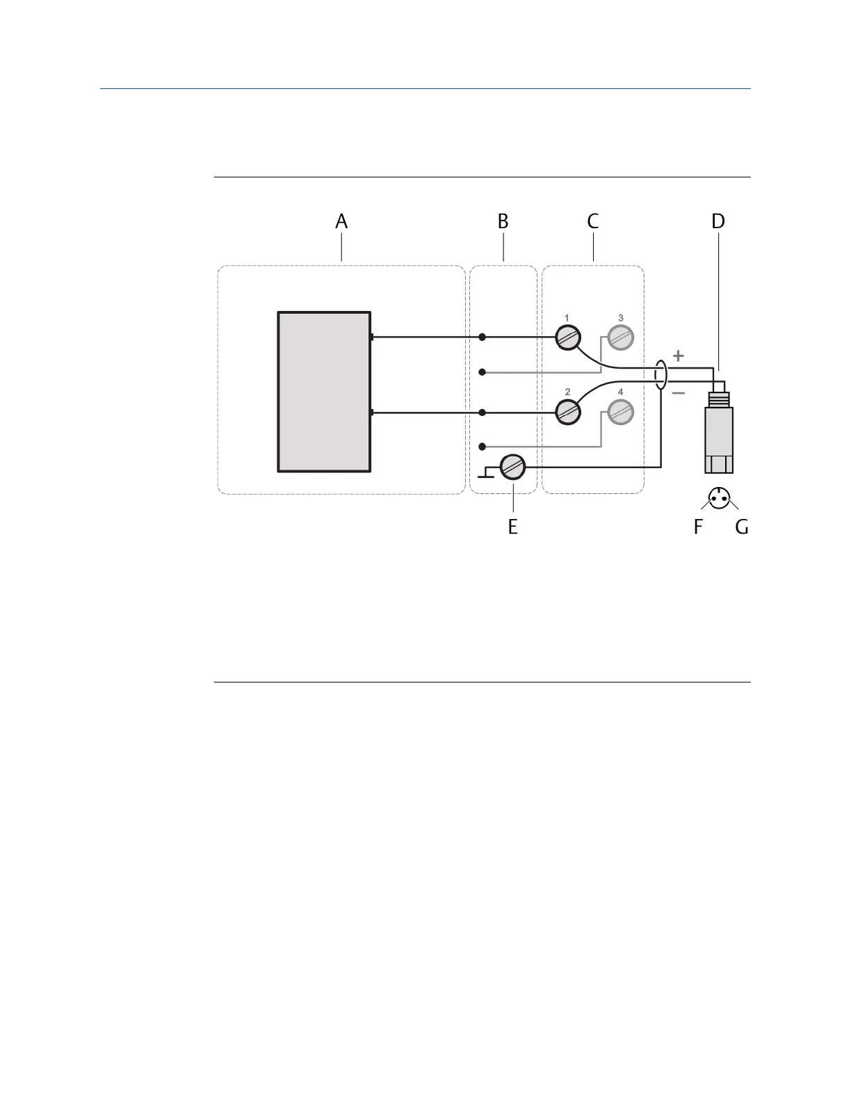
Figure 5-7: Sensor connection
A. VI Piezo CHARM
B. CHARM Baseplate
C. CHARM Terminal Block
D. 2-wire piezoelectric or strain sensor
E. Cable shield connection
F. Top view of the sensor connector – terminal A
G. Top view of the sensor connector – terminal B
Prerequisites
• Wire cutter
• Tool for removing the cable sheath
• Wire stripper
• Suitable screw driver for the CHARM Terminal Block screws
• Shielded sensor cable
• Observe the hints in Wiring guidelines.
Procedure
1. At opened door, lead the sensor cable through a cable gland close to the slot where
the CHARM to be connected is installed.
2. Strip the cable sheath at a length of approximately 200 mm.
3. Strip each wire at a length of approximately 10 mm.
4. Connect the wires to the CHARM Terminal Block.
Installation Guide Installing CHARMs hardware
MHM-97923-PBF March 2024
MHM-97923-PBF, Rev. 2.10 47

 Loading...


