EasyManuals Logo

Emerson AMS Installation Guide

Emerson AMS
96 pages
To Next Page IconTo Next Page
To Previous Page IconTo Previous Page
Page #28 background imageLoading...
Page #28 background image
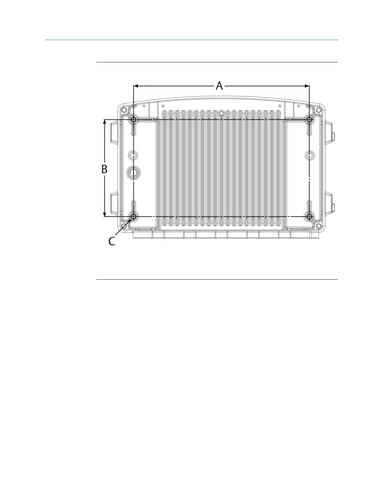
Figure 4-6: Position of the four blind holes for mounting
A. 298 mm
B. 164 mm
C. Blind hole with M8x1.25 thread; depth: 20 mm, threaded depth: 16 mm
4.4 Open the AMS Asset Monitor
All work at the AMS Asset Monitor requires an open door. If the door hinders you from
working at the AMS Asset Monitor, it can be completely removed.
Prerequisites
A PZ 3 cross-tip screwdriver for the door screws.
A pair of pliers or a flat-tip screwdriver to remove the circlip.
Procedure
1. Unfasten the screws which are securing the door.
Installing AMS Asset Monitor hardware Installation Guide
March 2024 MHM-97923-PBF
28 MHM-97923-PBF, Rev. 2.10

Table of Contents

Other manuals for Emerson AMS

Questions and Answers:

Question and Answer IconNeed help?

Do you have a question about the Emerson AMS and is the answer not in the manual?

Emerson AMS Specifications

General IconGeneral
Output4-20 mA, Digital
Measurement TypeVibration, Temperature
Communication ProtocolModbus, WirelessHART
Operating Temperature Range-40°C to +85°C
Enclosure RatingIP66
Power SupplyBattery, External Power

Related product manuals