1 General
1.1 About this manual
This manual contains specifications, wiring diagrams, dimensions, and step-by-step
instructions for installing the AMS Asset Monitor hardware.
Read this guide completely prior to starting installation of the device. Comply with all
safety instructions.
This installation guides applies for an AMS Asset Monitor with a hardware revision listed in
Table 1-1. See type plate for revision level.
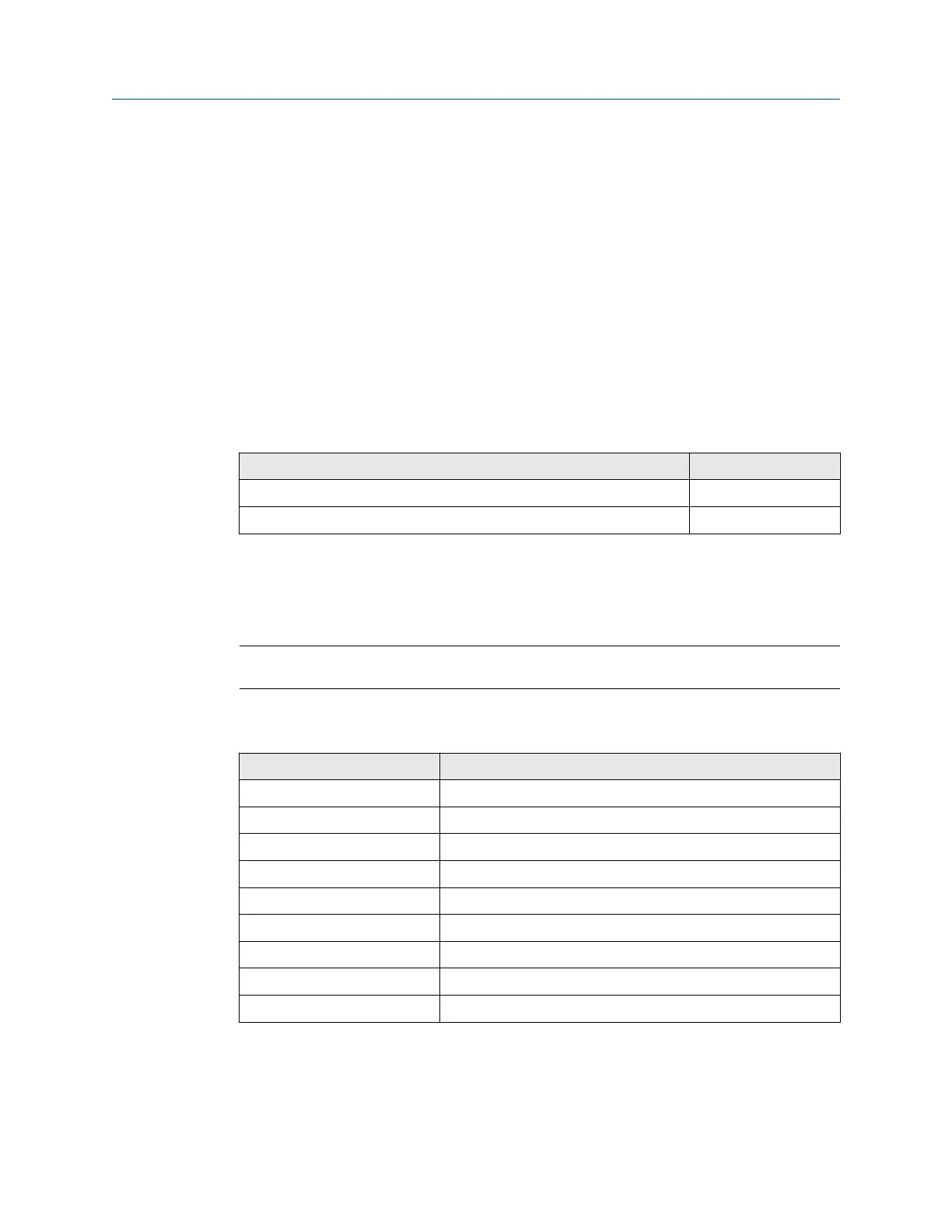
Table 1-1: Hardware revision
Component Revision
AMS Asset Monitor 13 and later
+24 V DC Power Module 08, 09
The hazardous location approvals described in Hazardous location installation and the EU
Declaration of Conformity (Certificates) do not apply to the blue AMS Asset Monitor –
Marine Paint variant AM 5820-IM BL.
Include the installation guide when transferring the device to third parties.
Note
When requesting technical support, indicate type and serial number from the type plate.
See Table 1-2 for a list of documents referred to in this installation guide.
Table 1-2: Referenced documents
Part number Document name
MHM-97924-PBF Operating Manual AMS Asset Monitor
MHM-97925-PBF Installation Guide VI Piezo CHARM
MHM-97930-PBF Installation Guide VI Tach CHARM
MHM-97929-PBF Installation Guide VI Voltage CHARM
AMS-SEC-PSG-001 AMS Product Security Documentation
--- System Guide AMS Machine Works
D800040X072 DeltaV
™
S-series and CHARMs Hardware Reference
12P5401 Div. 2 Installation Instruction
12P5403 Zone 2 Installation Instruction
See Table 1-3 for product type and ordering numbers of the hardware referred to in this
installation guide.
General
Installation Guide
March 2024 MHM-97923-PBF
8 MHM-97923-PBF, Rev. 2.10

 Loading...


