5.3.1 Connect the sensor wiring
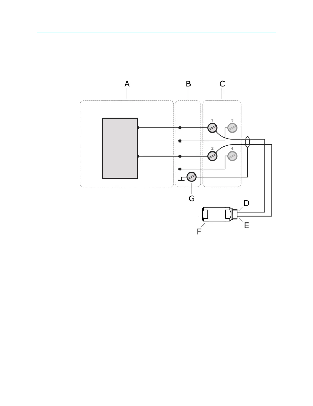
Figure 5-8: Sensor connection – magnetic pickup
A. VI Tach CHARM
B. CHARM Baseplate
C. Standard CHARM Terminal Block
D. Signal Out
E. Signal GND
F. Magnetic pickup
G. Cable shield connection
Installation Guide Installing CHARMs hardware
MHM-97923-PBF March 2024
MHM-97923-PBF, Rev. 2.10 49
 Loading...


