• Connect terminal - of the analog output of the field device to terminal 4 of the
CHARM Terminal Block.
• Connect the cable shield to a grounding terminal (see Grounding).
5. Ensure that the cable gland, where the signal cable is led through, is closed to keep
the IP protection class of the AMS Asset Monitor.
6. Continue with the installation or close the door (see Close the AMS Asset Monitor).
5.7.2 Connect the input signal wiring – loop-powered
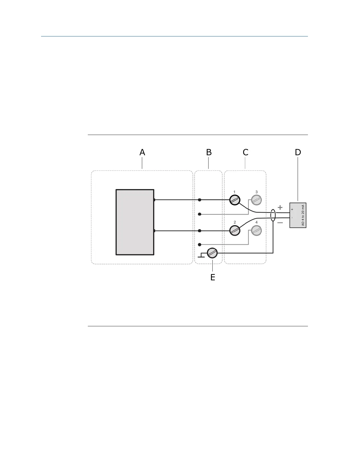
Figure 5-16: Signal connection
A. Analog Input AI 4 to 20 mA CHARM
B. CHARM Baseplate
C. CHARM Terminal Block
D. Field device with analog output
E. Cable shield connection
Technical data loop-power:
• 15.0 V minimum at 20 mA with 24 VDC input power
• Current limited to 30 mA maximum
Prerequisites
• Wire cutter
• Tool for removing the cable sheath
• Wire stripper
Installation Guide Installing CHARMs hardware
MHM-97923-PBF March 2024
MHM-97923-PBF, Rev. 2.10 61

 Loading...


