5.1 Install the +24 V DC Power Module
CAUTION
Any work on the system may impair asset health monitoring and machine protection.
Procedure
1. Open the AMS Asset Monitor (see Open the AMS Asset Monitor), if not already
done.
2. Ensure that the latch is in open position as shown in Figure 5-5. If the latch is in the
close position, move it upwards to open it.
3. Gently push the +24 V DC Power Module without tilting into the slot.
The +24 V DC Power Module fits only in one direction.
Note
The +24 V DC Power Module is hot-swappable. It is not necessary to switch off the
power supply of the system before installing or removing the +24 V DC Power
Module.
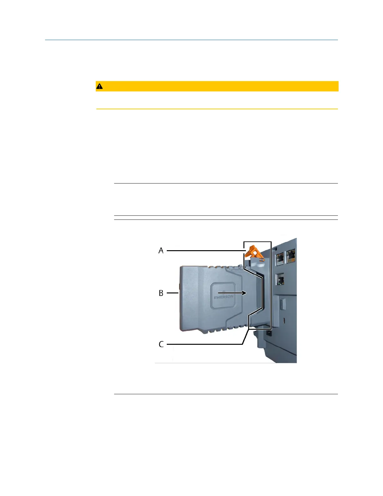
Figure 5-5: +24 V DC Power Module installation
A. Latch
B. +24 V DC Power Module
C. Slot for the +24 V DC Power Module
The +24 V DC Power Module locks with an audible click – the latch of the slot flips
down.
4. Continue with the installation or close the door (see Close the AMS Asset Monitor).
Installation Guide Installing CHARMs hardware
MHM-97923-PBF March 2024
MHM-97923-PBF, Rev. 2.10 45

 Loading...


