18
OPERATION
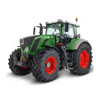
2.7 Indication of fluid levels
Operation_Pic_number:1
Text-module
A = Fuel supply
B = Engine temperature
When the bar indicators reach the red
zone, relieve the engine of load imme-
diately and allow to cool down for about
2 minutes at 1000 rpm, then turn the en-
gine off.
C = Compressed air supply
D = On-board electrical system voltage
E = Hydraulic oil supply
Fig.8
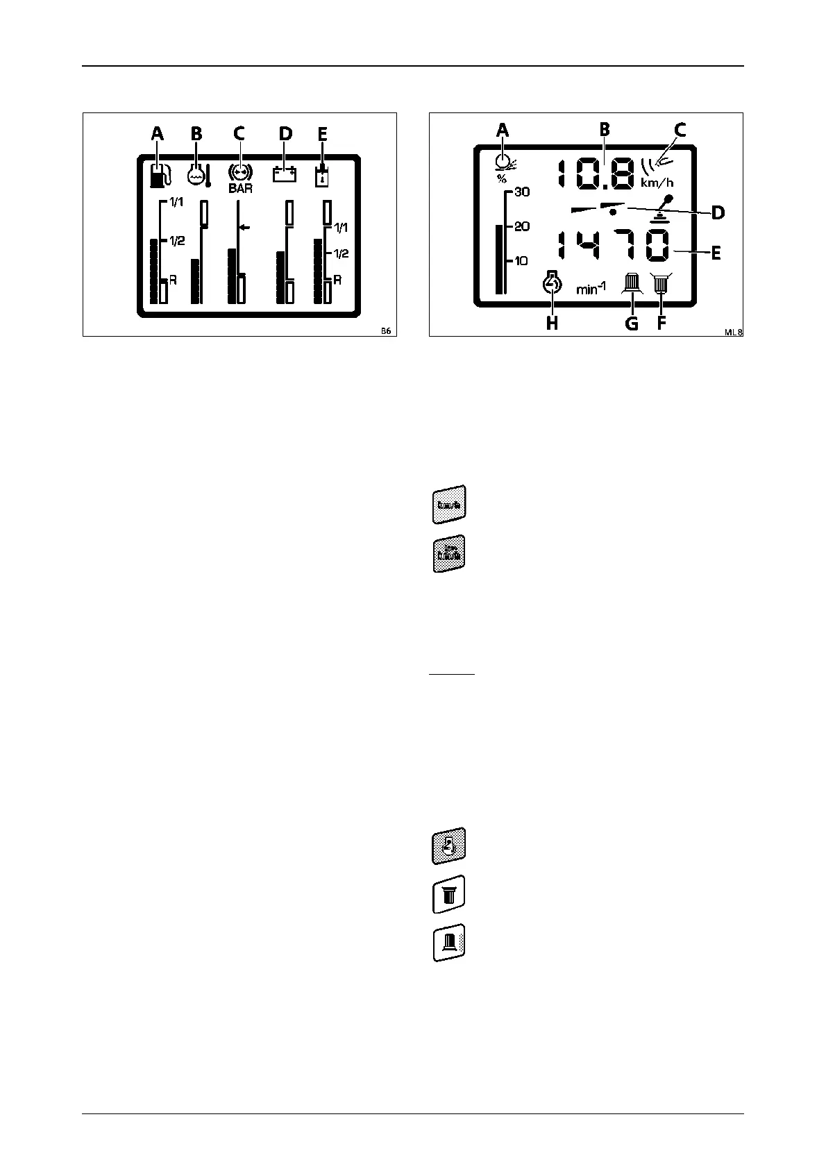
2.8 Operating status display
Operation_Pic_number:1
Text-module
A=Wheel slip in %;
(only if optional radar sensor is equip-
ped).
B=Tractor speed in km/h.
Text-module
On tractors with the optional radar sensor, use
these keys to change to:
NOTE:
For a precise reading, adjust the speed indi-
cator under operating conditions (see also
OPERATION Section 26.2).
Text-module
D=Driving mode indicator
the selected driving mode is indicated by
a spot (D).
E=Rpm indicator
can be changed with the buttons to:
Text-module
theoretical speed measurement
calculated from transmission speed.
actual speed based on signal from radar
sensor, symbol (C) is lit.
Theoretical speed calculation is activated auto-
matically when tractor speed is over
15 km/h, the wheel slip indicator (A) and symbol
(C) then go out.
engine speed symbol (H) is displayed.
rear PTO speed symbol (F) is displayed.
front PTO speed symbol (G) is displayed.
Fig.9
 Loading...