29
OPERATION
2.18 Power outlets
Operation_Pic_number:1
Text-module
A = 25 A constant current socket.
B = 10 A socket.
C = Implement socket.
D = Socket (blue) for external pulse counter.
E = LBS-ISO socket (optional) short circuit
plug must remain in place due to feed-
back.
F = Camera socket (optional).
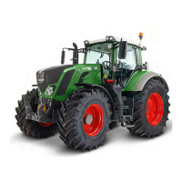
Pin - attribution LBS-ISO implement
socket cabin
Operation_Pic_number:1
A = Connector within cabin.
B = Connector for LBS-ISO Terminal.
Pin 1 = not used.
Pin 2 = CAN Low input.
Pin 3 = CAN Low output.
Pin 4 = CAN High input.
Pin 5 = CAN High output.
Pin 6 = CAN-EN.
Pin 7 = Power supply for connected implement
(maximum load 5A).
Pin 8 = CAN GND.
Pin 9 = Ground connection for connected imple-
ment.
Fig.26
Fig.27
Operation_Pic_number:1
A = Trailer socket.
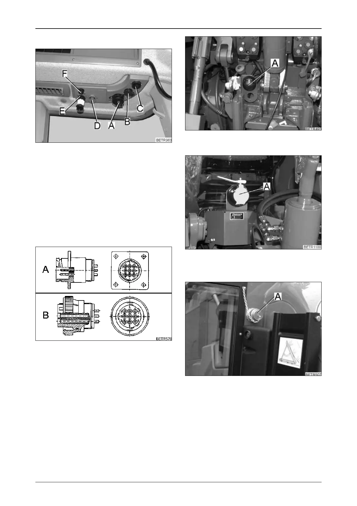
Operation_Pic_number:1
A = Electro-hydraulic external control:
Socket for external sensor.
Operation_Pic_number:1
LBS-ISO socket (A) rear (optional).
Fig.28
Fig.29
Fig.30
 Loading...