3-20
FUEL SYSTEM
3-20
Index
Number
1
2
3
4
5
6
Part Name
Choke Plate
Choke Shaft Assembly
Fast idle Pick-up Lever
Choke Hsg. Shaft & Lev. Assy.
Fast Idle Cam Lever
Choke Therm. Lev., Link & Piston
Assembly
7
Choke Plate Screw
8 Therm. Hsg. Clamp Screw
9 Throttle Stop Screw
11
Fuel
Bowl to Main Body Screw
12 Throt. Body Ser. & L. W.
13
Choke Hsg. Ser. & L. W.
15
Fast Idle Cam Lever Screw
16 Fast idle Cam Lev. & Throt. Lev.
Screw & L. W.
17
Pump Oper. Lev. Adj. Screw
18 Pump Discharge Nozzle Screw
19
Throttle Plate Screw
20
Fuel Pump Cov. Assy. Ser. & L. W.
21 Pump Cam Lock Ser. & L. W.
22 Fuel Valve Seat Lock Screw
23
Fuel Level Check Plug
24 Fuel Level Check Plug Gasket
25
Fuel Inlet Fitting Gasket
26 Fuel Bowl Screw Gasket
27
Choke Housing Gasket
28 Power Valve Body Gasket
29
Throttle Body Gasket
TYPICAL NOMENCLATURE
Index
Number
30
31
32
33
34
35
36
37
38
40
41
42
43
44
45
47
48
49
50
51
55
56
57
58
59
60
61
Part Name
Choke Therm. Housing Gasket
Flange Gasket
Fuel Valve Seat Adj. Nut Gskt.
Fuel
Valve Seat Lock Ser. Gskt.
Fuel Bowl Gasket
Metering Body Gasket
Pump Discharge Nozzle Gasket
Throttle Plate
Throt. Body & Shaft Assy.
Float & Hinge Assy.
Fuel Inlet Valve & Seat Assy.
Pump Oper. Lev. Adj. Ser. Fitting
Fuel Inlet Fitting
Pump Discharge Nozzle
Main Jet
Pump Discharge Needle Valve or
Check Ball Weight
Power Valve Assembly
Fu;;zF Seat “0” Ring Seal or
Idle Needle Seal
Choke Rod Seal
Choke Hsg. & Plugs Assy.
Fuel Pump Cover Assy.
Fuel Bowl & Plugs Assy.
Main Metering Body & Plugs Assy.
Pump Diaphragm Assembly
Float Spring Retainer
Air Vent Retainer
MODEL 4160 CARBURETOR SYSTEMS
Index
Number
62
63
64
65
66
69
70
72
73
74
76
78
79
80
81
84
86
87
88
93
95
96
97
104
105
110
115
119
Part Name
Fast Idle Cam Lev. Ser. Spring
Throttle Stop Screw Spring
Pump Diaphragm Return Spring
Fast Idle Cam Lev. Spring
Pump Oper. Lev. Adj. Spring
Float Spring
Choke Thermostat Shaft Nut
Fuel Valve Seat Adj. Nut
Choke Therm. Lever Spacer
Fast Idle Cam Assembly
Choke Rod
Choke Therm. Shaft Nut L. W.
Thermostat Housing Assembly
Choke Rod Retainer
Thermostat Housing Clamp
Filter Screen Assembly
Baffle Plate
Pump Operating Lever
Pump Operating Lev. Retainer
Air Adapter Hole Plug
Throttle Lever
Throttle Shaft Bearing
Throttle Shaft Brg. (center)
Diaphragm Link Retainer
Air Vent Rod Spg. Retainer
Throt. Link Connector Pin Washer
Metering Body Vent Baffle
Pump Oper. Lever
Stud
PRIMARY SYSTEMS
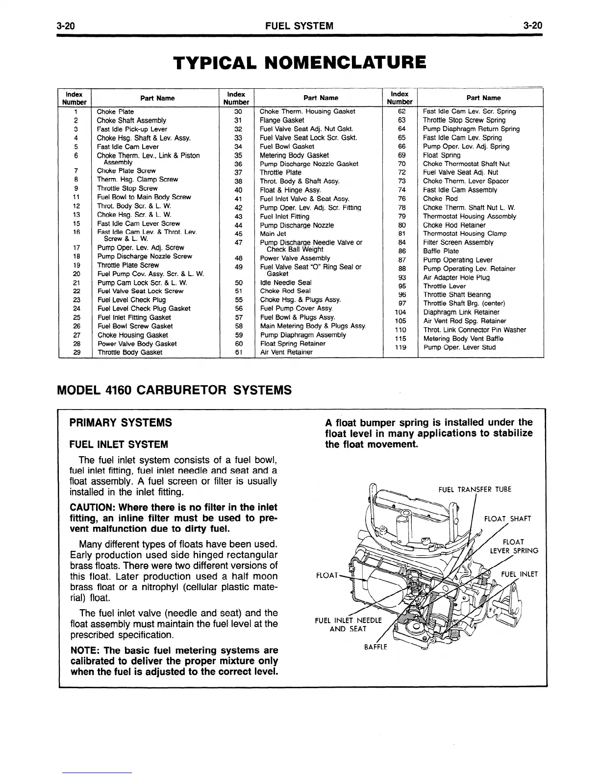
A float bumper spring is installed under the
float level in many applications to stabilize
FUEL INLET SYSTEM
The fuel inlet system consists of a fuel bowl,
the float movement.
fuel inlet fitting, fuel inlet needle and seat and a
float assembly. A fuel screen or filter is usually
installed in the inlet fitting.
CAUTION: Where there is no filter in the inlet
fitting, an inline filter must be used to pre-
vent malfunction due to dirty fuel.
Many different types of floats have been used.
Early production used side hinged rectangular
brass floats. There were two different versions of
this float. Later production used a half moon
brass float or a nitrophyl (cellular plastic mate-
rial) float.
The fuel inlet valve (needle and seat) and the
float assembly must maintain the fuel level at the
prescribed specification.
NOTE: The basic fuel metering systems are
calibrated to deliver the proper mixture only
when the fuel is adjusted to the correct level.
 Loading...


