2-09 IGNITION SYSTEM 2-09
DIAGNOSIS AND TESTING (Continued)
TEST STEP
RESULT
ACTION TO TAKE
5
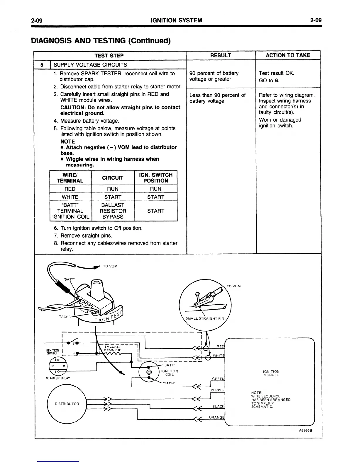
SUPPLY VOLTAGE CIRCUITS
I
1. Remove SPARK TESTER, reconnect coil wire to 90 percent of battery Test result OK.
distributor cap. voltage or greater
GO to 6.
2. Disconnect cable from starter relay to starter motor.
,
3. Carefully insert small straight pins in RED and
WHITE module wires.
Less than 90 percent of Refer to wiring diagram.
battery voltage Inspect wiring harness
CAUTION: Do not allow straight pins to contact
and connector(s) in
electrical ground.
faulty circuit(s).
4. Measure battery voltage.
Worn or damaged
5. Following table below, measure voltage at points
ignition switch.
listed with ignition switch in position shown.
NOTE
l
Attach negative (- ) VOM lead to distributor
base.
l
Wiggle wires in wiring harness when
measuring.
\
WIRE/
CIRCUIT
IGN. SWITCH
TERMINAL
POSITION
RED
RUN
RUN
WHITE START START
“BAT-T”
BALLAST
TERMINAL
RESISTOR START
IGNITION COIL
BYPASS
/
\
6. Turn ignition switch to Off position.
7. Remove straight pins.
8. Reconnect any cables/wires removed from starter
relay.
IGNITION
MODULE
DISTRIBUTOR
NOTE:
WIRE SEQUENCE
HAS BEEN ARRANGED
TO SIMPLIFY
SCHEMATIC.
A6360-B
 Loading...


