2-07
IGNITION SYSTEM
2-07
DIAGNOSIS AND TESTING (Continued)
TEST STEP
I
RESULT
I
ACTION TO TAKE
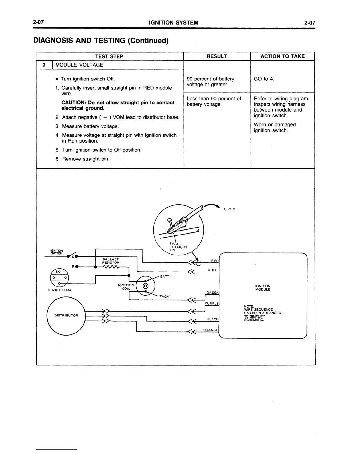
3 MODULE VOLTAGE
,
l
Turn ignition switch Off.
90 percent of battery
GO to 4.
1. Carefully insert small straight pin in RED
module
voltage or greater
wire.
L
CAUTION: Do not
allow straight pin to contact
Less than 90 percent of
Refer
to
wiring diagram.
electrical ground.
battery voltage
Inspect wiring harness
between module and
2. Attach negative (
- ) VOM lead to distributor base.
ignition switch.
3. Measure battery voltage.
Worn or damaged
ignition switch.
4. Measure voltage at straight pin with ignition switch
in Run position.
5. Turn ignition switch to Off position.
6. Remove straight pin.
IGNITION
MODULE
WIRE SEQUENCE
DISTR I BUTOR
HAS BEEN ARRANGED
TO SIMPLIFY
SCHEMATIC.
 Loading...


