5-08
STARTING SYSTEM
5-08
DISASSEMBLY AND ASSEMBLY (Continued)
ASSEMBLY
1.
Position the three coils and pole pieces, then
install the attaching screws. As the pole shoe
screws are tightened, strike the frame several
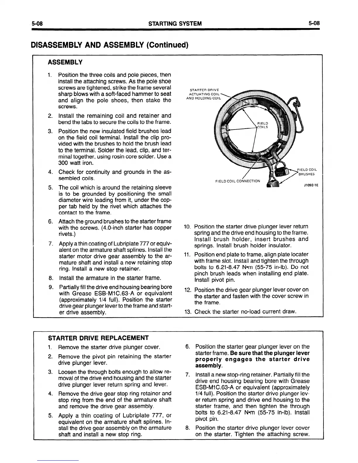
STARTER DRIV
sharp blows with a soft-faced hammer to seat
ACTUATING COI
and align the pole shoes, then stake the
AND HOLDING CO
screws.
2. Install the remaining coil and retainer and
bend the tabs to secure the coils to the frame.
3. Position the new insulated field brushes lead
on the field coil terminal. Install the clip pro-
vided with the brushes to hold the brush lead
to the terminal. Solder the lead, clip, and ter-
minal together, using rosin core solder. Use a
300
watt iron.
4.
Check for continuity and grounds in the as-
sembled coils.
FIELD COIL CONNECTION
5.
The coil which is around the retaining sleeve
is to be grounded by positioning the small
diameter wire leading from it, under the cop-
per tab held by the rivet which attaches the
contact to the frame.
6. Attach the ground brushes to the starter frame
with the screws. (4.0.inch starter has copper
10. Position the starter drive plunger lever return
rivets .)
spring and the drive end housing to the frame.
7. Apply a thin coating of Lubriplate 777 or equiv-
Install brush holder, insert brushes and
alent on the armature shaft splines. Install the
springs. Install brush holder insulator.
starter motor drive gear assembly to the ar-
11. Position end plate to frame, align plate locater
mature shaft and install a new retaining stop
with frame slot. Install and tighten the through
ring. Install a new stop retainer.
bolts to 6.21-8.47 Nom (55-75 in-lb). Do not
8. Install the armature in the starter frame.
pinch brush leads when installing end plate.
Install pivot pin.
9. Partially fill the drive end housing bearing bore
with Grease ESB-MIC.63-A or equivalent
12. Position the drive gear plunger lever cover on
(approximately l/4 full). Position the starter
the starter and fasten with the cover screw in
drive gear plunger lever to the frame and start-
the frame.
er drive assembly.
13. Check the starter no-load current draw.
STARTER DRIVE REPLACEMENT
1. Remove the starter drive plunger cover.
2. Remove the pivot pin retaining the starter
drive plunger lever.
3. Loosen the through bolts enough to allow re-
moval of the drive end housing and the starter
drive plunger lever return spring and lever.
4. Remove the drive gear stop ring retainer and
stop ring from the end of the armature shaft
and remove the drive gear assembly.
5. Apply a thin coating of Lubriplate 777, or
equivalent on the armature shaft splines. In-
stall the drive gear assembly on the armature
shaft and install a new stop ring.
6. Position the starter gear plunger lever on the
starter frame.
Be sure that the plunger lever
properly engages the starter drive
assembly.
7. install a new stop-ring retainer. Partially fill the
drive end housing bearing bore with Grease
ESB-Ml C.63-A or equivalent (approximately
l/4 full). Position the starter drive plunger lev-
er return spring and drive end housing to the
starter frame, and then tighten the through
bolts to 6.21-8.47 Nom (55-75 in-lb). Install
pivot pin.
8. Position the starter drive plunger lever cover
on the starter. Tighten the attaching screw.
 Loading...


