3-05
FUEL SYSTEM
3-05
MODEL 2300 2-V CARBURETOR
DESCRIPTION
booster venturis. Within the venturis are the
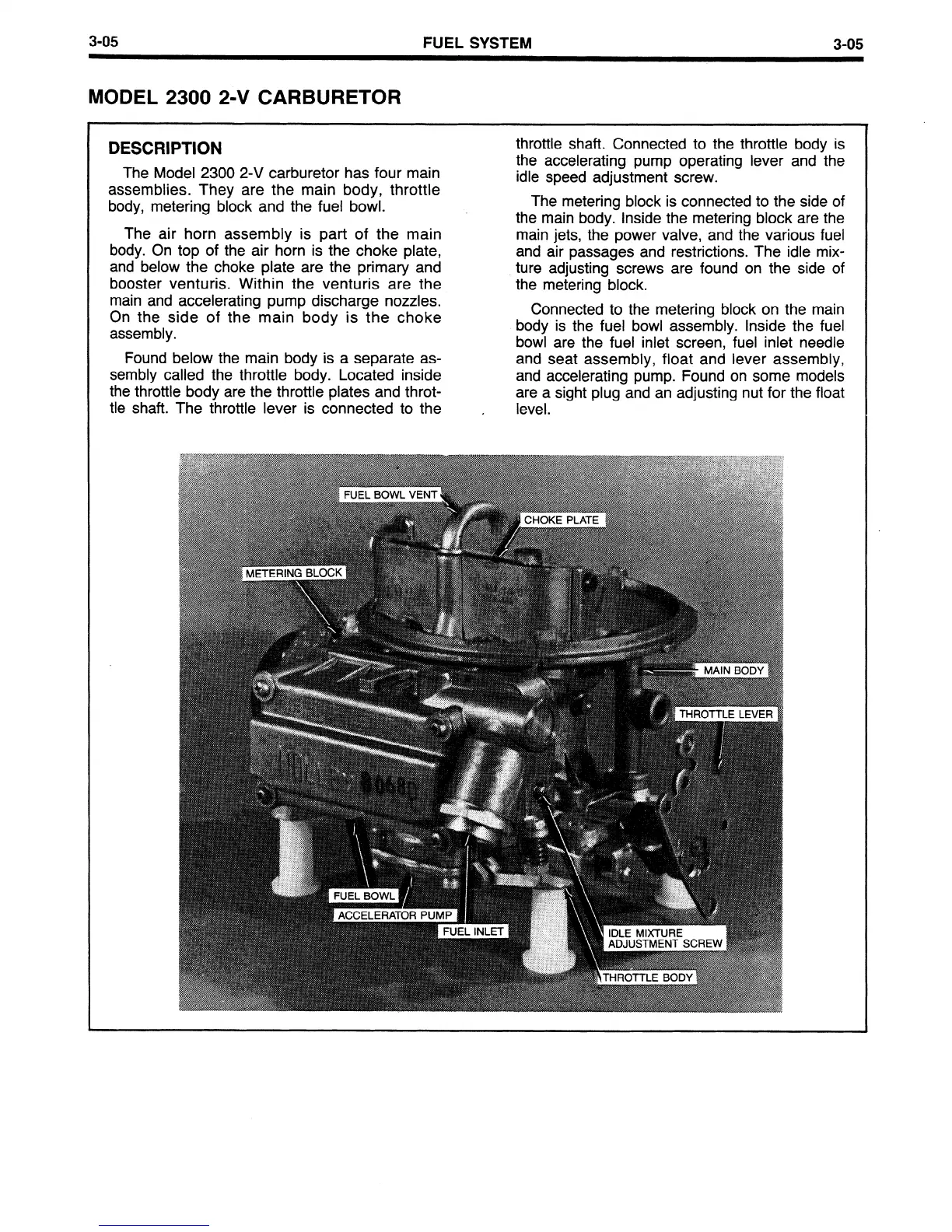
The Model 2300 2-V carburetor has four main
assemblies. They are the main body, throttle
body, metering block and the fuel bowl.
The air horn assembly is part of the main
body. On top of the air horn is the choke plate,
and below the choke plate are the primary and
throttle shaft. Connected to the throttle body is
the accelerating pump operating lever and the
idle speed adjustment screw.
The metering block is connected to the side of
the main body. Inside the metering block are the
main jets, the power valve, and the various fuel
and air passages and restrictions. The idle mix-
ture adjusting screws are found on the side of
Connected to the metering block on the main
the metering-block.
body is the fuel bowl assembly. Inside the fuel
bowl are the fuel inlet screen, fuel inlet needle
and seat assembly, float and lever assembly,
and accelerating pump. Found on some models
are a sight plug and an adjusting nut for the float
level.
main and accelerating pump discharge nozzles.
On the side of the main body is the choke
assembly.
Found below the main body is a separate as-
sembly called the throttle body. Located inside
the throttle body are the throttle plates and throt-
tle shaft. The throttle lever is connected to the
.
 Loading...


