2-13
IGNITION SYSTEM
2-13
DIAGNOSIS AND TESTING (Continued)
TEST STEP
RESULT
ACTION TO TAKE
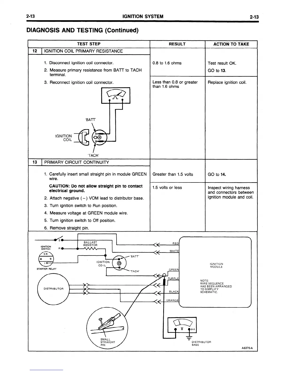
12
1 IGNITION COIL PRIMARY RESISTANCE
1. Disconnect ignition coil connector.
2. Measure
primary resistance from BAIT to TACH
terminal.
3. Reconnect ignition coil connector.
%
4
$sq
w \
\ \
0.8 to 1.6 ohms
Less than 0.8 or greater
than 1.6 ohms
Test result OK.
GO to 13.
Replace ignition coil.
‘BAIT
ab ’
,
IGNITION
COIL
M9)
‘TACH’
13
PRIMARY CIRCUIT CONTINUITY
1. Carefully insert small straight pin in module GREEN
Greater than 1.5 volts
GO to 14.
wire.
CAUTION: Do not allow straight pin
to contact
electrical ground.
1.5 volts or less
Inspect wiring harness
and connectors between
2. Attach negative ( -) VOM lead to distributor base.
ignition module and coil.
3. Turn ignition switch to Run position.
4. Measure voltage at GREEN module wire.
5. Turn ignition switch to Off position.
6. Remove straight pin.
b
A
.
.
BALLAST
IGNITION
RESISTOR
RED
SWITCH
R*
A
w
.
WHITE
IGNITION
MODULE
STARTER RELAY
DISTRIBUTOR
NOTE:
WIRE SEQUENCE
HAS BEEN ARRANGED
TO SIMPLIFY
SCHEMATIC.
A6370-A
 Loading...


