4-16
CHARGING
4-16
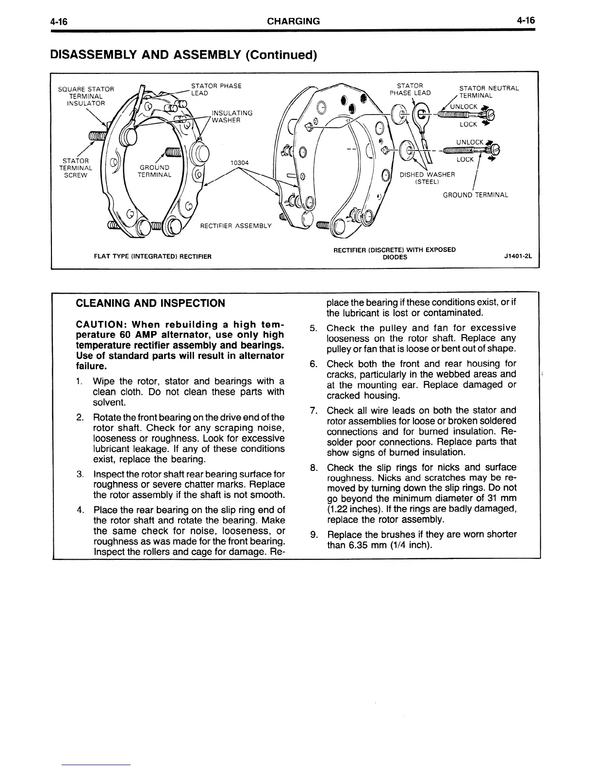
DISASSEMBLY AND ASSEMBLY (Continued)
INSULATING
GROUND TERMINAL
RECTIFIER ASSEMBLY
RECTIFIER (DISCRETE) WITH EXPOSED
FLAT TYPE (INTEGRATED) RECTIFIER DIODES
J1401-2L
CLEANING AND INSPECTION
CAUTION: When rebuilding a high tem-
perature 60 AMP alternator, use only high
temperature rectifier assembly and bearings.
Use of standard parts will result in alternator
failure.
1. Wipe the rotor, stator and bearings with a
clean cloth. Do not clean these parts with
solvent.
2. Rotate the front bearing on the drive end of the
rotor shaft. Check for any scraping noise,
looseness or roughness. Look for excessive
lubricant leakage. If any of these conditions
exist, replace the bearing.
3.
inspect the rotor shaft rear bearing surface for
roughness or severe chatter marks. Replace
the rotor assembly if the shaft is not smooth.
4.
Place the rear bearing on the slip ring end of
the rotor shaft and rotate the bearing. Make
the same check for noise, looseness, or
roughness as was made for the front bearing.
inspect the rollers and cage for damage. Re-
place the bearing if these conditions exist, or if
the lubricant is lost or contaminated.
5. Check the pulley and fan for excessive
looseness on the rotor shaft. Replace any
pulley or fan that is loose or bent out of shape.
6. Check both the front and rear housing for
cracks, particularly in the webbed areas and
at the mounting ear. Replace damaged or
cracked housing.
7. Check all wire leads on both the stator and
rotor assemblies for loose or broken soldered
connections and for burned insulation. Re-
solder poor connections. Replace parts that
show signs of burned insulation.
8. Check the slip rings for nicks and surface
roughness. Nicks and scratches may be re-
moved by turning down the slip rings. Do not
go beyond the minimum diameter of 31 mm
(1.22 inches). If the rings are badly damaged,
replace the rotor assembly.
9.
Replace the brushes if they are worn shorter
than 6.35 mm (l/4 inch).
 Loading...


