I-43
BASIC ENGINE
1-43
REMOVAL AND INSTALLATION (Continued)
Main and connecting rod bearing inserts are
selective fits.
Selective fit bearings are available for service
in standard size, 0.001 and 0.002 inch under-
size. Undersize bearings (0.010, 0.020 and
0.030 inch), which are not selective fit, are avail-
able for use on crankshaft journals that have
been refinished.
Removal
1. Drain the crankcase. Remove the oil level
dipstick. Remove the oil pan and related
parts, following the procedure under Oil Pan-
Removal.
2. Remove the oil pump.
3. Replace one bearing at a time, leaving the
other bearings securely fastened. Remove
the main bearing cap to which new bearings
are to be installed.
4.
Insert the upper bearing removal tool (Tool
6331-E) in the oil hole in the crankshaft.
5.
Rotate the crankshaft in the direction of en-
gine rotation to force the bearing out of the
block.
Installation
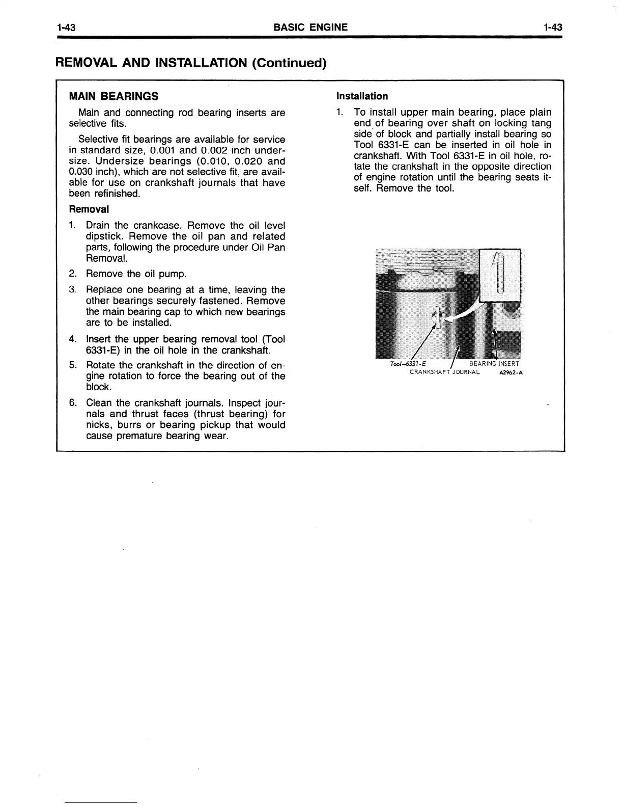
1. To install upper main bearing, place plain
end of bearing over shaft on locking tang
side’ of block and partially install bearing so
Tool 6331-E can be inserted in oil hole in
crankshaft. With Tool 6331-E in oil hole, ro-
tate the crankshaft in the opposite direction
of engine rotation until the bearing seats it-
self. Remove the tool.
CRANKSHAFT-JOURNAL
A2962-A
6. Clean the crankshaft journals. Inspect jour-
nals and thrust faces (thrust bearing) for
nicks, burrs or bearing pickup that would
cause premature bearing wear.
 Loading...


