I-26
BASIC ENGINE
. 1-26
OVERHAUL (Continued)
The following procedure should be used to re-
pair porous areas or sand holes in cast iron:
a. Clean the surface to be repaired by grind-
ing or rotary filing to a clean bright metal
surface. Chamfer or undercut the hole or
porosity to a greater depth than the rest
of the cleaned surface. Solid metal must
surround the hole. Openings larger than
l/4 inch should not be repaired using me-
tallic plastic. Openings in excess of l/4
inch can be drilled, tapped and plugged
using common tools. Clean the repair
area thoroughly. Metallic plastic will not
stick to a dirty or oily surface.
b. Mix the metallic plastic base and hard-
ener as directed on the container. Stir
thoroughly until uniform.
c. Apply the repair mixture with a suitable
clean tool (putty knife, wood spoon, etc.)
forcing the epoxy into the hole or porosity.
d. Allow the repair mixture to harden. This
can be accomplished by two methods:
heat cure with a 250 degree watt lamp
placed IO inches from the repaired sur-
face, or air dry for lo-12 hours at tem-
peratures above 50 degrees F.
e. Sand or grind the repaired area to blend
with the general contour of the surround-
ing surface.
face to match the rest of the
f. Paint the sur
block.
--
ADJUSTMENTS
VALVE CLEARANCE
The valve arrangement on the left bank is E-l-
E-I-E-I-E-I and on the right bank is I-E-I-E-I-E-I-
E
.
A 1.52mm (0.060 inch) shorter push rod or a
1.52mm (0.060 inch) longer push rod are avail-
able for service to provide a means of compen-
sating for dimensional changes in the valve
mechanism.
Valve stem to valve rocker arm clearance
should be within specifications listed at the end
of this Section. With the hydraulic tappet com-
pletely collapsed, repeated valve reconditioning
operations (valve and/or valve seat refacing) will
decrease the clearance to the point that if not
compensated for, the hydraulic valve tappet will
cease to function and the valve will be held
open.
To determine whether a shorter or a longer
push rod is necessary, make the following
check:
1. Install an auxiliary starter switch.
Crank the
engine with the ignition switch Off until
the No. 1 piston is on TDC after the com-
pression stroke.
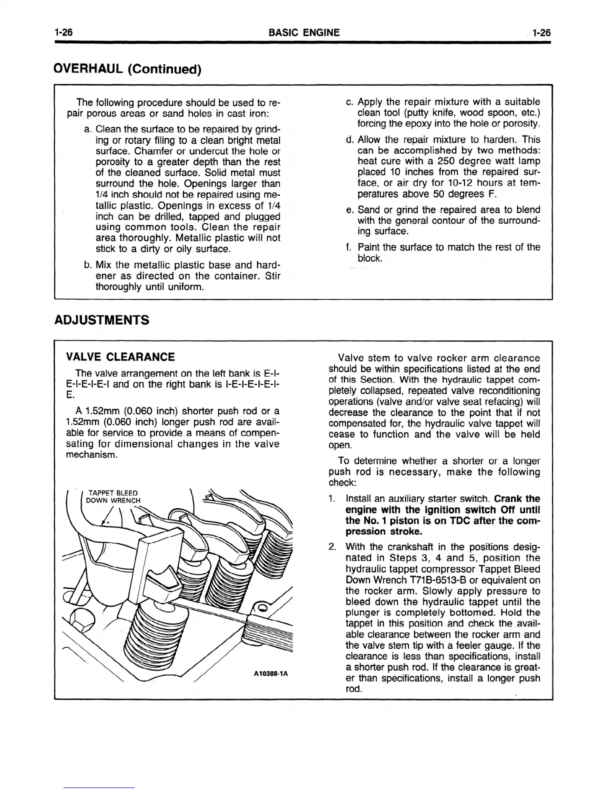
2. With the crankshaft in the positions desig-
nated in Steps 3, 4 and 5, position the
hydraulic tappet compressor Tappet Bleed
Down Wrench T71B-6513-B or equivalent on
the rocker arm. Slowly apply pressure to
bleed down the hydraulic tappet until the
plunger is completely bottomed. Hold the
tappet in this position and check the avail-
able clearance between the rocker arm and
the valve stem tip with a feeler gauge. If the
clearance is less than specifications, install
a shorter push rod. If the clearance is great-
er than specifications, install a longer push
rod.
 Loading...


