4-06
CHARGING
4-06
TESTING (Continued)
STATE OF CHARGE - MAINTENANCE-
FREE BATTERIES
Read the battery open circuit terminal voltage
with
a digital voltmeter capable
of
reading
l/100 of
a volt. If the open circuit voltage of the battery is
below 12.40
volts and the battery has passed the
capacity test, charge the battery.
CHARGING SYSTEM TESTS
MOTOROLA
The following tests are made with the alternator
on the engine with output and regulator connec-
tions maintained to the alternator except as noted
in Tests 3 and 5. The field lead and voltage reg-
ulator are disconnected for these tests.
CAUTION:
- DO NOT disconnect alternator output lead
while alternator is operating.
- DO NOT disconnect voltage regulator while
alternator is operating.
- DO NOT ground field terminal.
- Check battery condition. Use a fully
charged battery when testing alternator.
- Disconnect ground cable of battery when
removing and installing the alternator.
All readings indicated are for correct operation.
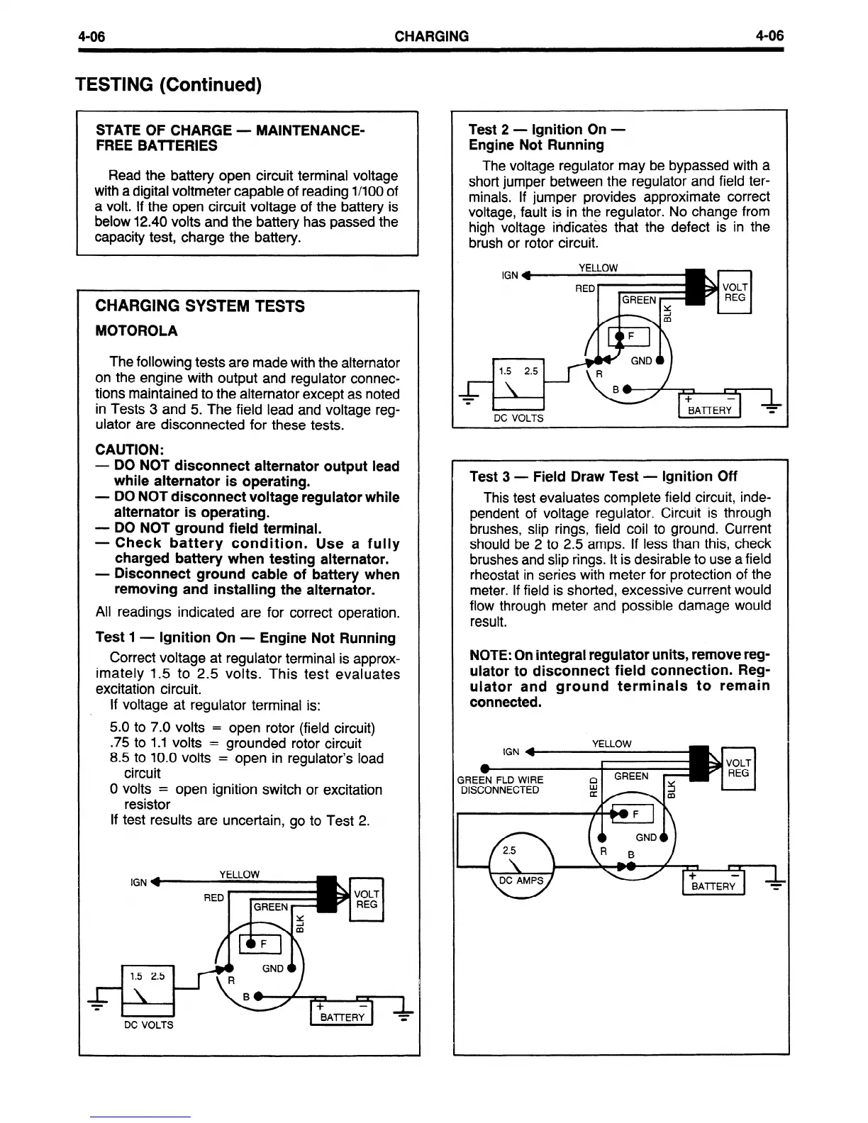
Test 1 - Ignition On -
Engine Not Running
Correct voltage at regulator terminal is approx-
imately 1.5 to 2.5 volts. This test evaluates
excitation circuit.
If voltage at regulator terminal is:
5.0 to 7.0 volts =
open rotor (field circuit)
.75
to 1.1 volts =
grounded rotor circuit
8.5
to 10.0 volts =
open in regulator’s load
circuit
0 volts =
open ignition switch or excitation
resistor
If test results are uncertain, go to Test 2.
Test 2
- Ignition On -
Engine Not Running
The voltage regulator may be bypassed with a
short jumper between the regulator and field ter-
minals. If jumper provides approximate correct
voltage, fault is in the regulator. No change from
high voltage indicates that the defect is in the
brush or rotor circuit.
DC VOLTS
Test 3 -
Field Draw Test - Ignition Off
This test evaluates complete field circuit, inde-
pendent of voltage regulator. Circuit is through
brushes, slip rings, field coil to ground. Current
should be 2 to 2.5 amps. If less than this, check
brushes and slip rings. It is desirable to use a field
rheostat in series with meter for protection of the
meter. If field is shorted, excessive current would
flow through meter and possible damage would
result.
NOTE: On integral regulator units, remove reg-
ulator to disconnect field connection. Reg-
ulator and ground terminals to remain
connected.
DISCONNECTED
 Loading...


