3-10
FUEL SYSTEM
3-10
MODEL 2300 24 CARBURETOR (Continued)
ERRATIC ENGINE IDLE
If the engine idle is erratic or rough after cor-
rect idle adjustment, check the following items:
1.
Recheck spark plugs and spark plug wires.
Be sure all cylinders are firing. A missing
cylinder or occasional misfire will turn an en-
gine that is a minor emitter into a gross
emitter.
2. Check for vacuum leaks (vacuum lines or
manifold).
LOW IDLE SPEED ADJUSTMENT
With engine at correct operating temperature
and condition as in above procedure and curb
idle adjusted to specifications, proceed as
follows:
1. Set the low idle speed to specifications by
adjusting the low idle speed adjusting screw.
ACCELERATING PUMP LEVER
ADJUSTMENT
1. Using a feeler gauge and with the throttle
plates in the wide open position, there
should be .015 inch clearance between the
accelerating pump operating lever adjust-
ment screw head and the pump arm when
the pump arm is depressed manually.
2. If adjustment is required, loosen the adjust-
ing screw lock nut and turn the adjusting
screw in to increase the clearance and out
- to decrease the clearance.
One half turn of
the adjusting screw is equal to approx-
imately 0.015 inch.
When the proper adjust-
ment has been obtained hold the adjustment
screw in position with a wrench and tighten
the lock nut.
3. Perform an accelerating pump stroke adjust-
ment, if required.
ACCELERATING
PUMP LEVER
ACCELERATING PUMP STROKE
ADJUSTMENT
The accelerating pump stroke has been set to
help keep the exhaust emission level of the en-
gine within’the specified limits. The additional
holes provided for pump stroke adjustment are
for adjusting the stroke for specific engine ap-
plications.
The stroke should not be changed
from the original setting.
If the pump stroke has been changed from
the specified setting, refer to the following
instructions to correct the stroke to
specifications.
If a change in the adjustment is required,
make certain the proper hole (top or bottom)
in plastic accelerating pump cam, located be-
hind the throttle lever, is properly aligned (in-
dexed) with the numbered hole (top or
bottom) in the throttle lever before installing
the retaining screw.
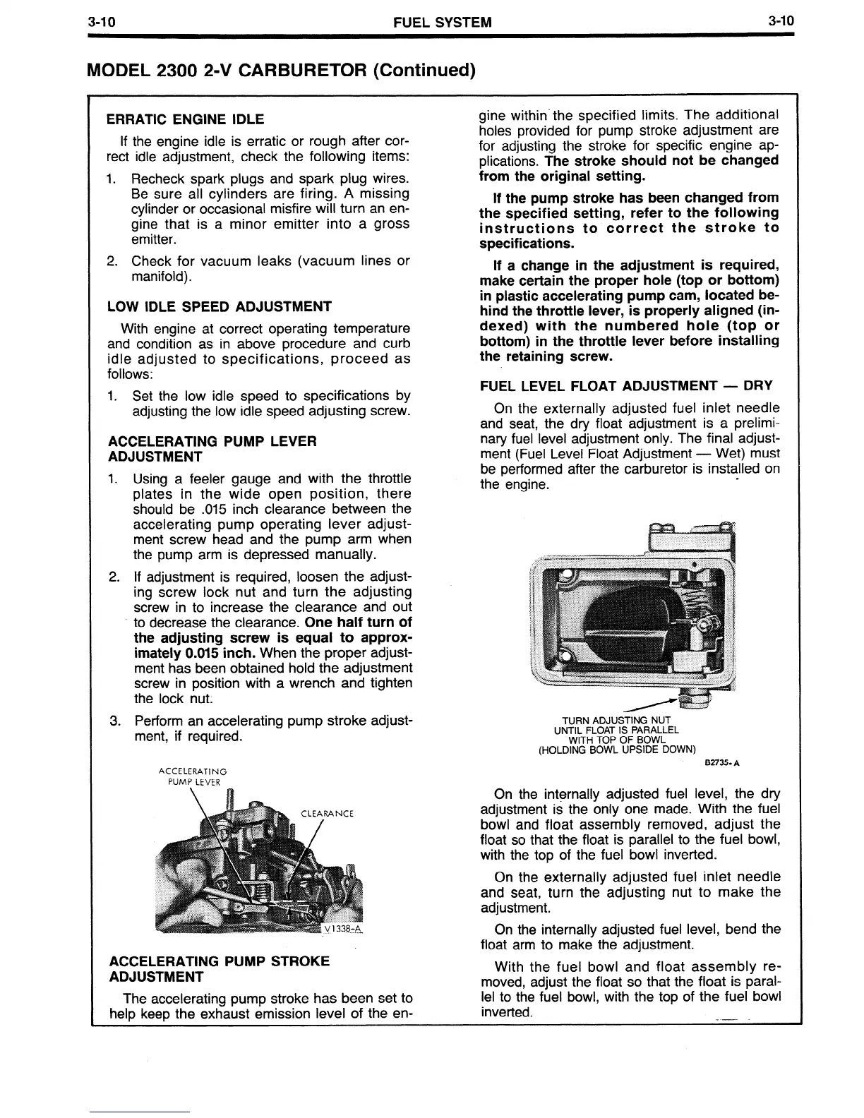
FUEL LEVEL FLOAT ADJUSTMENT - DRY
On the externally adjusted fuel inlet needle
and seat, the dry float adjustment is a prelimi-
nary fuel level adjustment only. The final adjust-
ment (Fuel Level Float Adjustment - Wet) must
be performed after the carburetor is installed on
the engine.
.
TURN ADJUSTING NUT
UNTIL FLOAT IS PARALLEL
WITH TOP OF BOWL
(HOLDING BOWL UPSIDE DOWN)
82735
A
On the internally adjusted fuel level, the dry
adjustment is the only one made. With the fuel
bowl and float assembly removed, adjust the
float so that the float is parallel to the fuel bowl,
with the top of the fuel bowl inverted.
On the externally adjusted fuel inlet needle
and seat, turn the adjusting nut to make the
adjustment.
On the internally adjusted fuel level, bend the
float arm to make the adjustment.
With the fuel bowl and float assembly re-
moved, adjust the float so that the float is paral-
lel to the fuel bowl, with the top of the fuel bowl
inverted.
-- -
 Loading...


