4-11
CHARGING
4-11
TESTING (Continued)
BENCH TESTS
After the general charging system diagnosis
has isolated the problem to the alternator, remove
it from the vehicle for bench testing and service, or
replacement. Refer to Alternator Removal and
Disassembly in this section.
Rectifier Short or Grounded and Stator
Grounded Test
These tests are performed with an ohmmeter
(Rotunda 50-0010 or equivalent). Set the “Multiply
By” knob at 1 and calibrate the ohmmeter as
directed.
CAUTION: Digital meters cannot be used to
perform these rectifier tests.
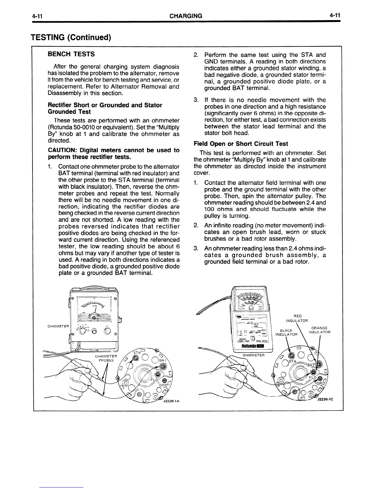
1 . Contact one ohmmeter probe to the alternator
BAT terminal (terminal with red insulator) and
the other probe to the STA terminal (terminal
with black insulator). Then, reverse the ohm-
meter probes and repeat the test. Normally
there will be no needle movement in one di-
rection, indicating the rectifier diodes are
being checked in the reverse current direction
and are not shorted. A low reading with the
probes reversed indicates that rectifier
positive diodes are being checked in the for-
ward current direction. Using the referenced
tester, the low reading should be about 6
ohms but may vary if another type of tester is
used. A reading in both directions indicates a
bad positive diode, a grounded positive diode
plate or a grounded BAT terminal.
OHMMETER
?A
2. Perform the same test using the STA and
GND terminals. A reading in both directions
indicates either a grounded stator winding, a
bad negative diode, a grounded stator termi-
nal, a grounded positive diode plate, or a
grounded BAT terminal.
3. If there is no needle movement with the
probes in one direction and a high resistance
(significantly over 6 ohms) in the opposite di-
rection, for either test, a bad connection exists
between the stator lead terminal and the
stator bolt head.
Field Open or Short Circuit Test
This test is performed with an ohmmeter. Set
the ohmmeter “Multiply By” knob at 1 and calibrate
the ohmmeter as directed inside the instrument
cover.
1. Contact the alternator field terminal with one
probe and the ground terminal with the other
probe. Then, spin the alternator pulley. The
.ohmmeter reading should be between 2.4 and
100 ohms and should fluctuate while the
pulley is turning.
2. An infinite reading (no meter movement) indi-
cates an open brush lead, worn or stuck
brushes or a bad rotor assembly.
3. An ohmmeter reading less than 2.4 ohms indi-
cates a grounded brush assembly, a
grounded field terminal or a bad rotor.
RED
INSULATOR
BLACK
INSULATOR
\ \
ORANGE
INSULATOR
 Loading...


