I-09
BASIC ENGINE
I-09
DIAGNOSIS AND TESTING (Continued)
HYDRAULIC VALVE LIFTER
Dirt, deposits of gum and varnish and air bub-
bles in the lubricating oil can cause hydraulic
valve lifter failure or malfunction.
Dirt, gum and varnish can keep a check
valve from seating and cause a loss of
hydraulic pressure.
An open valve disc will
c&se the plunger to force oil back into the valve
lifter reservoir during the time the push rod is
being lifted to force the valve from its seat.
Air bubbles in the lubricating system can be
caused by too much oil in the system or too low
an oil level. Air may also be drawn into the lubri-
cating system through an opening in a damaged
oil pick-up tube. Air in the hydraulic system can
cause a loss of hydraulic pressure.
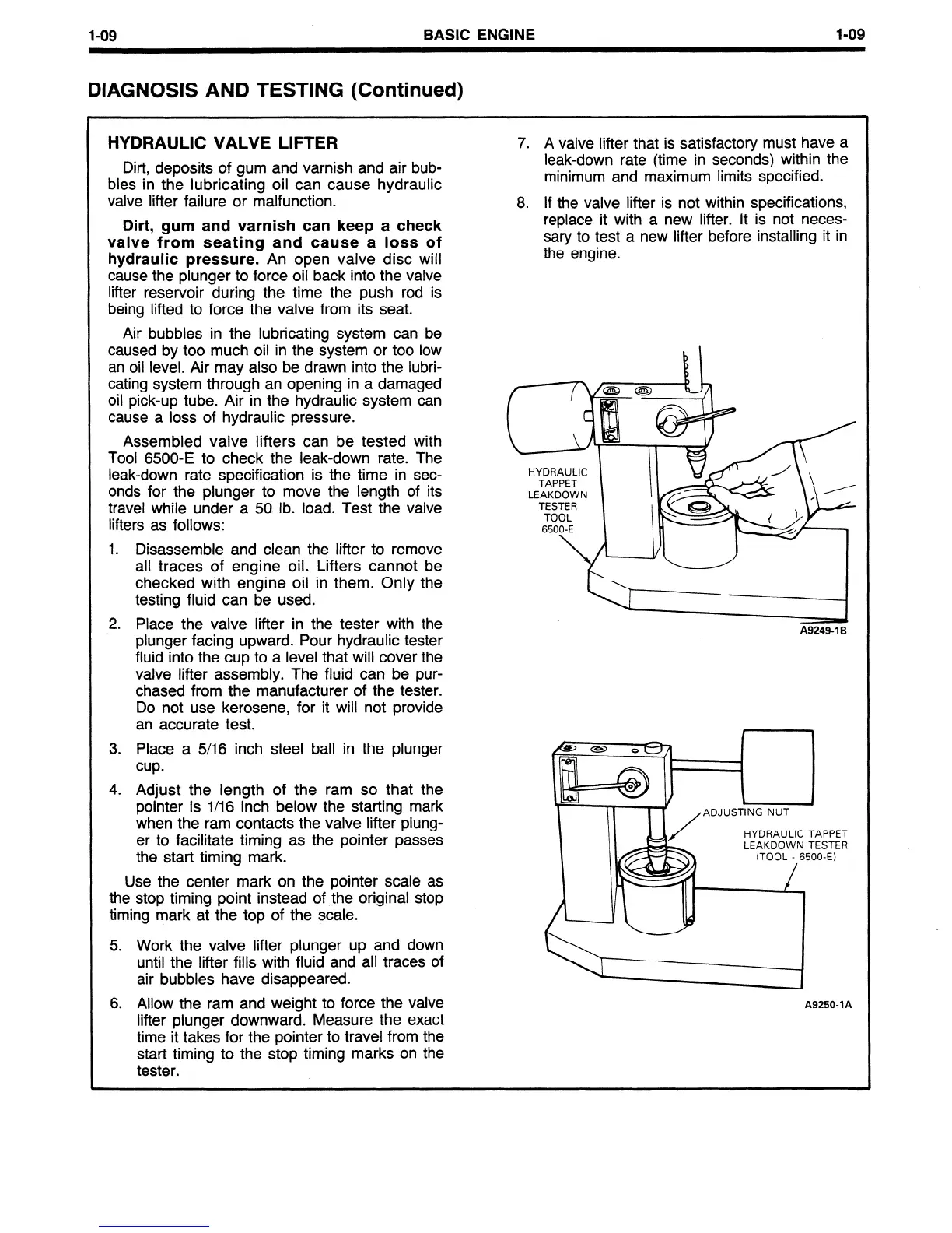
Assembled valve lifters can be tested with
Tool 6500-E to check the leak-down rate. The
leak-down rate specification is the time in sec-
onds for the plunger to move the length of its
travel while under a 50 lb. load. Test the valve
lifters as follows:
1. Disassemble and clean the lifter to remove
all traces of engine oil. Lifters cannot be
checked with engine oil in them. Only the
testing fluid can be used.
2. Place the valve lifter in the tester with the
plunger facing upward. Pour hydraulic tester
fluid into the cup to a level that will cover the
valve lifter assembly. The fluid can be pur-
chased from the manufacturer of the tester.
Do not use kerosene, for it will not provide
an accurate test.
3. Place a 5/16 inch steel ball in the plunger
cup.
4. Adjust the length of the ram so that the
pointer is l/16 inch below the starting mark
when the ram contacts the valve lifter plung-
er to facilitate timing as the pointer passes
the start timing mark.
Use the center mark on the pointer scale as
the stop timing point instead of the original stop
timing mark at the top of the scale.
5. Work the valve lifter plunger up and down
until the lifter fills with fluid and all traces of
air bubbles have disappeared.
6. Allow the ram and weight to force the valve
lifter plunger downward. Measure the exact
time it takes for the pointer to travel from the
start timing to the stop timing marks on the
tester.
7. A valve lifter that is satisfactory must have a
leak-down rate (time in seconds) within the
minimum and maximum limits specified.
8. If the valve lifter is not within specifications,
replace it with a new lifter. It is not neces-
sary to test a new lifter before installing it in
the engine.
b \
HYDRAULIC
TAPPET
LEAKDOWN
6500-E 1
HI -
A9249- 1 B
LEAKDOWN TESTE
FE3 I
(TOOL - 6500-E)
:T
R
A9250-1 A
 Loading...


