l-42 BASIC ENGINE
1-42
REMOVAL AND INSTALLATION (Continued)
Installation
1. Carefully clean the seal groove in the cap
and block with a brush and solvent.
2. Dip the split lip-type seal halves in clean en-
gine oil.
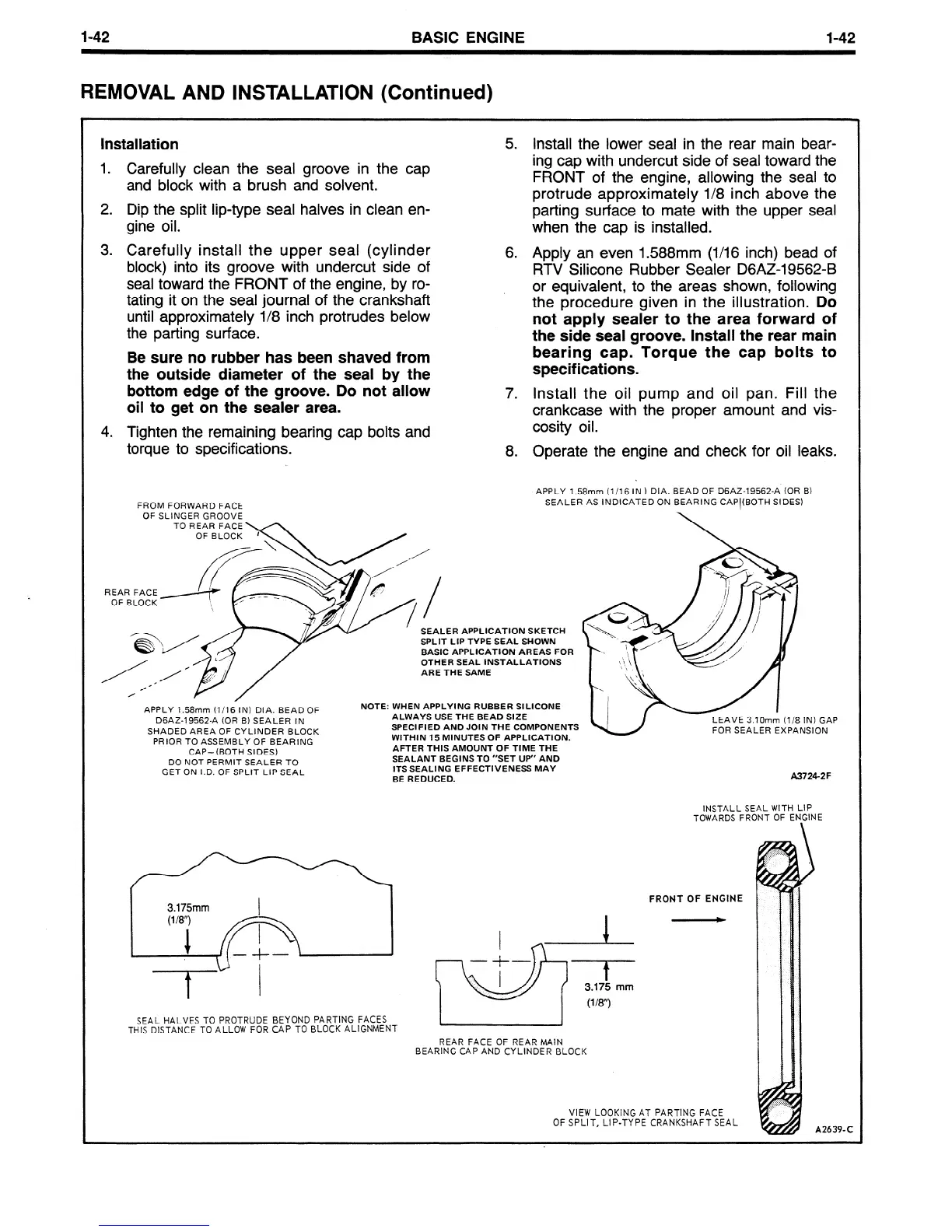
3. Carefully install the upper seal (cylinder
block) into its groove with undercut side of
seal toward the FRONT of the engine, by ro-
tating it on the seal journal of the crankshaft
until approximately l/8 inch protrudes below
the parting surface.
Be sure no rubber has been shaved from
the outside diameter of the seal by the
bottom edge of the groove. Do not allow
oil to get on the sealer area.
4. Tighten the remaining bearing cap bolts and
torque to specifications.
5 .
Install the lower seal in the rear main bear-
ing cap with undercut side of seal toward the
FRONT of the engine, allowing the seal to
protrude approximately l/8 inch above the
parting surface to mate with the upper seal
when the cap is installed.
6. Apply an even 1.588mm (l/16 inch) bead of
RTV Silicone Rubber Sealer DGAZ-19562-B
or equivalent, to the areas shown, following
the procedure given in the illustration.
Do
not apply sealer to the area forward of
the side seal groove. Install the rear main
bearing cap. Torque the cap bolts to
specifications.
7. Install the oil pump and oil pan. Fill the
crankcase with the proper amount and vis-
cosity oil.
8.
Operate the engine and check for oil leaks.
APPLY 1.58mm (l/16 IN 1 DIA. BEAD OF D6AZ-19562-A (OR B)
FROM FORWARD FACE
SEALER AS INDICATED ON BEARING CAPItBOTH SIDES)
OF SLINGER GROOVE
SEALER APPLICATION SKETCH
SPLIT LIP TYPE SEAL SHOWN
BASIC APPLICATION AREAS FOR
OTHER SEAL INSTALLATIONS
ARE THE SAME
APPLY
1.58mm (l/16 IN) DIA. BEAD OF
DGAZ-19562-A (OR B) SEALER IN
SHADED AREA
OF CYLINDER BLOCK
PRIOR TO ASSEMBLY OF BEARING
CAP-(BOTH SIDES)
DO NOT PERMIT SEALER TO
GET ON I.D. OF
SPLIT LIP SEAL
NOTE: WHEN APPLYING RUBBER SILICONE
ALWAYS USE THE BEAD SIZE
SPECIFIED AND JOIN THE COMPONENTS
WITHIN 15 MINUTES OF APPLICATION.
AFTER THIS AMOUNT OF TIME THE
SEALANT BEGINS TO “SET UP” AND
ITS SEALING EFFECTIVENESS MAY
BE REDUCED.
LEAVE 3.10mm (l/8 IN) GAP
FOR SEALER EXPANSION
A3724-2F
INSTALL SEAL WITH LIP
TOWARDS FRONT OF
ENFINE
3.175mm
SEAL HALVES TO PROTRUDE BEYOND PARTING
FACES
THIS DISTANCE TO ALLOW FOR CAP TO BLOCK ALIGNMENT
FRONT OF ENGINE
+
A
T-l
I
- f
3.175 mm
(l/8”)
REAR FACE OF REAR MAIN
BEARING CAP AND CYLINDER BLOCK
VIEW LOOKING AT PARTING FACE
OF SPLIT, LIP-TYPE CRANKSHAFT SEAL
A2639-C
 Loading...


