B30 Patient Monitor
8-24
Document no. 2044677-001
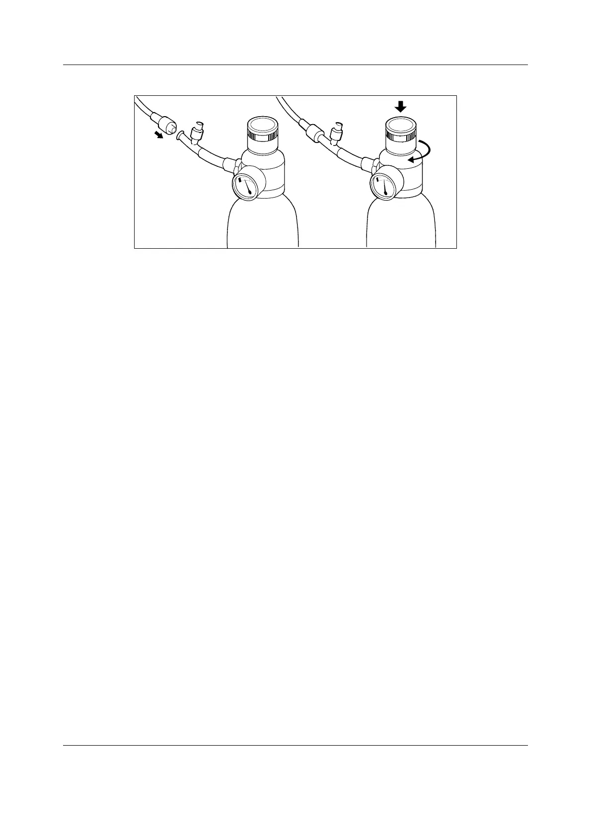
Figure 9 Connecting sampling line to the gas valve and feeding gas
3. For maximum accuracy, let the monitor warm up for 30 minutes. The menu item Ga s
calibration remains gray as long as the message ‘Calibrating gas sensor’ is displayed.
4. Press the
Airway Gas key and select Gas calibration.
5. Wait until the ‘Zero ok’ and then the ‘Feed gas’ messages appear after each gas on the
screen.
6. Open the regulator and feed calibration gas until the message ‘Adjust’ appears, then
close the valve.
7. Check that the displayed gas value matches the value on the calibration gas container.
NOTE: Adjust the O
2
percentage according to the calibration gas (for 755580 the right O2 value
is 20%).
NOTE: If an error occurs during calibration or if no gas is fed, the text ‘Calibr. error’ appears.
Push the ComWheel to perform a new calibration.
If adjustments are required:
• Turn the ComWheel to highlight the first gas to be adjusted and then push the ComWheel.
Turn the ComWheel until the displayed value matches the desired value in the gas bottle and
push it again.
If the message ‘Zero error’ is displayed, press the
Normal Screen key and repeat the
calibration procedure.
The time of the last calibration is shown at the bottom of the menu page.
5.1.2 Gas sampling system adjustment
For flow rate measurements, a flow meter with a low flow resistance and the capability to
measure low flow rates is required. A sampling line of normal length has to be connected to the
monitor as it has a considerable effect on the flow.
5.1.3 Flow rate measurement
If any flow rates are not correct, first replace the Mini D-Fend water trap, then recheck the
flows.
The sampling flow rate is measured by a flow meter at the sampling line. The flow rate should
be between 135 and 165 ml/min. The flow rate is adjusted in the Ga s e s service menu with
Sample gain adj.
 Loading...


