System description
1-15
Document no. 2044677-001
2.5 Software loading
The program memory on the CPU board is loaded with monitor software and selected
language files at the factory. The software is used for running all the functions that are
integrated into the PC board. For service upgrade main software and language files, please
refer to “Software download instruction” in Appendix A or the “B30 Patient Monitor Software
download instruction”(PN 2045710-001)
2.6 Parameter modules
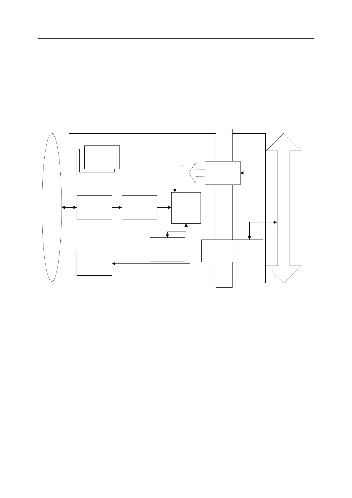
Figure 4 General structure of parameter modules with patient isolation
The detailed structure of a parameter module depends on the specific needs for each
individual parameter. However, some common parts are used in the parameter modules. The
electronics inside the module is usually divided into isolated (floating) and non-isolated
sections. Typically, the non-isolated section consists of buffers to interface the parameter
module to the module bus while the rest of the electronics is located in the isolated section. The
isolated section includes the microcontroller together with memory components, the front-end
analog electronics (amplifiers, etc.) and sensor drivers.
Module Bus
Isolation
transformer
RS485
drivers
Peripheral
drivers
A/D
converter
CPU
Analog
electronics
Opto
isolation
RAM
EEPROM
Patient isolation
PATIENT
Module
keys
Data
+13...16 V
VMOD
+5 V
+12 V
eneral_struct_of_parm_mod.vsd
 Loading...


