E-PSM(P)W module introduction
1-33
Document no. 2044677-001
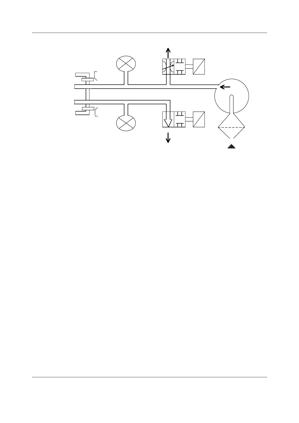
Figure 18 NIBP pneumatics diagram
Power supply section of the NIBP board
All connections are established via a 5-pin connector (female). The module needs a +15 V (dirty)
power supply to operate. The supply voltage Vmod 13.8- 16 V is generated in the power supply
section of the monitor. The other voltages needed for the operation of the NIBP measurement
are made on the NIBP board.
The NIBP power supply synchronizes the ECG and STP isolation power and supplies
non-isolated 5 V to the ECG and STP board.
4.4.3 ECG board in 5-lead measurement
The ECG measurement consists of the functions shown in Figure 19. All functions are located in
the ECG board except the ECG input unit.
Safety pressure sensor
Main pressure sensor
Dump valve
Proportional valve
Air pump
Intake air filter
Cuff connector
PSM_NIBP_pneum_diagr.vsd
S1
S2
Plunger
Plunger
 Loading...


