Frame functional description
1-19
Document no. 2044677-001
System watchdog and voltage supervision
There are two voltage supervision chips that control the system reset signals.
The +3.3V supervision chip outputs reset signals for +3.3V devices. Reset is activated when
voltage is below 3.08V. It also has a watchdog that is refreshed in normal operation and in
standby.
The +5V supervision chip outputs reset signals for +5V devices. Reset is activated when voltage
is below 4.63V. +5V reset causes also +3.3V reset through a FET.
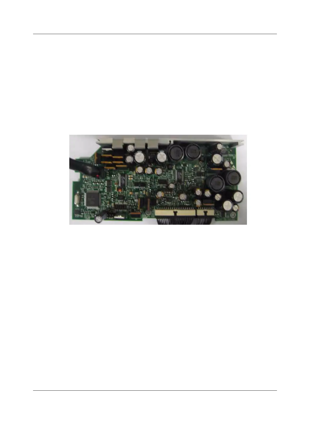
3.1.4 DC/DC board
The DC/DC board converts the output voltage of AC/DC unit, external DC unit or battery
voltage to various supply voltages for the electronics of B30 monitor. The DC/DC board takes
care of the battery charging.
Figure 7 DC/DC Board
DC/DC board functional blocks
DC/DC board operation is controlled by the PMC (Power Management Controller) CPU. PMC
takes care of power path controlling and power supplies' sequencing. It communicates with
the main CPU via serial communication. PMC also measures DC/DC board voltages and
currents.
High efficiency switching power supplies and power path switches are used on the DC/DC
board. This is because of no-fan requirement for FM monitor as well as maximizing the battery
time.
Circuit breakers make VSYS and MOD voltages short-circuit protected. Also the battery
charger, +5V and +3.3V switchers withstand short-circuit. +5V_OUT is disconnected from +5V
by a circuit breaker in case of +5V_OUT overload.
The boost converter can be set to two different output levels. The higher one is used to give the
battery charger adequate input voltage when the DC/DC board input comes from an external
DC source. The lower one is set in AC/DC use to keep the boost converter enabled but passed
by a diode and thus not switching, which minimizes the power loss. When the AC/DC voltage
drops, the boost converter starts regulating its output and keeps the MOD voltages at a level a
little lower than the one in AC/DC use. In battery use, the lower output voltage yields a little
better efficiency, too.
 Loading...


