B30 Patient Monitor
1-30
Document no. 2044677-001
4.3 Equipment safety symbols
4.4 Main components
4.4.1 E-PSMPW/E-PSMW modules
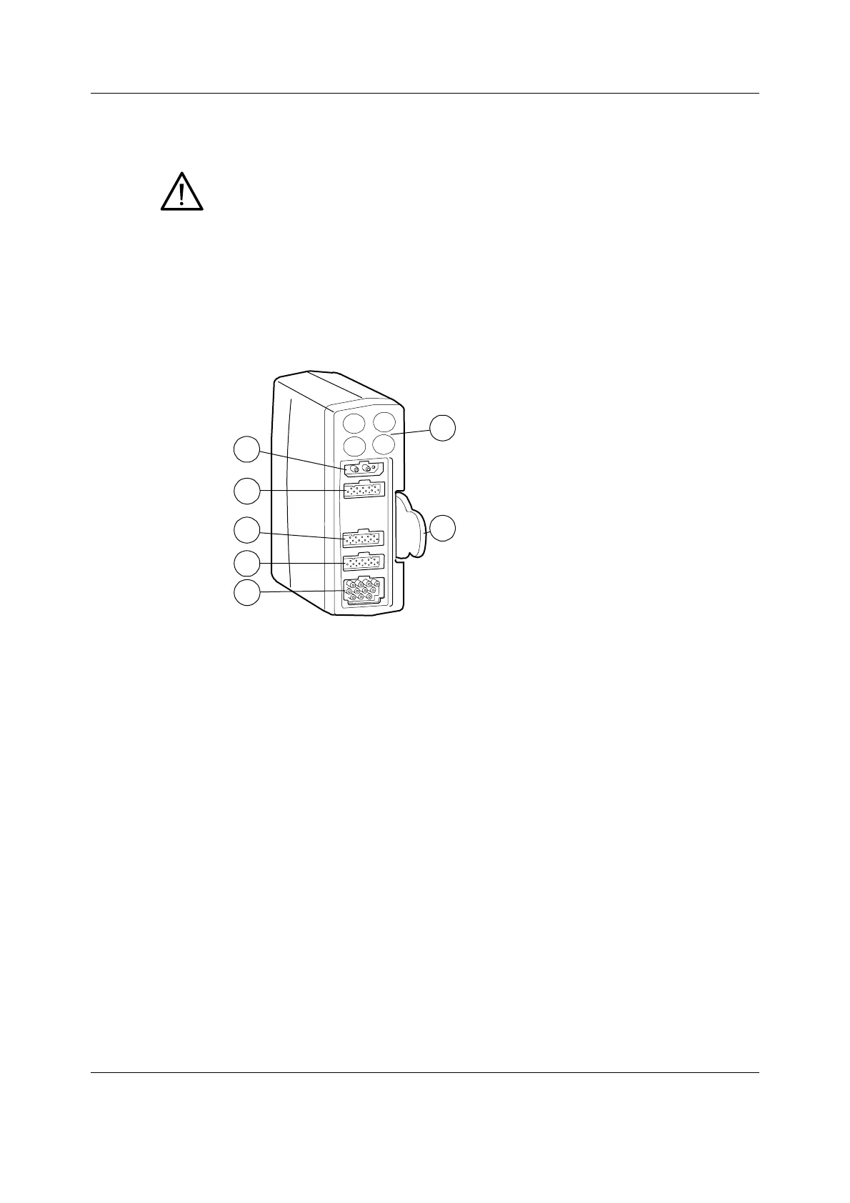
Figure 16 Front panel of E-PSMPW
E-PSMPW and E-PSMW modules contain three main PC boards, the STP board, the ECG board,
and the NIBP board. Each of these boards contain a processor and software in the processor
flash memory. The boards produce their own supply voltages from the Vmod 13.8-16 V line
that is available via the module bus connector. One exception, the NIBP board provides +5V for
the ECG and STP board non-isolated side components. The NIBP board provides also the
synchronization signal for the ECG and STP board power supplies.
There are two input boards; the STP input board and the ECG input board attached to the front
panel of the module. The front panel has five connectors and four keys. There is one connector
for two temperature measurements, one for two invasive blood pressure measurements, one
for ECG, one for NIBP, and one for SpO
2
measurement. The NIBP connector includes two
plungers for NIBP hose identification. The keys are for NIBP Auto On/Off, NIBP Start/Cancel, P1
zero, and P2 zero.
When displayed on the E-PSM(P)W module, indicates that protection against
cardiac defibrillator discharge is due in part to the accessories for pulse
oximetry (SpO
2
), temperature (T) and invasive pressure (P) measurement
1. Module keys
2. NIBP connector
3. InvBP connector in E-PSMPW only
4. Temperature connector
5. SpO
2
connector
6. ECG and impedance respiration connector
7. Tab for removing the module
7
1
2
4
5
3
6
 Loading...


