GE MEDICAL SYSTEMS
D
IRECTION FK091075, REVISION 04 VIVID 3N PRO/EXPERT SERVICE MANUAL
5-24 Section 5-4 - Front End
5-4-10 Image Port Board (IMP)
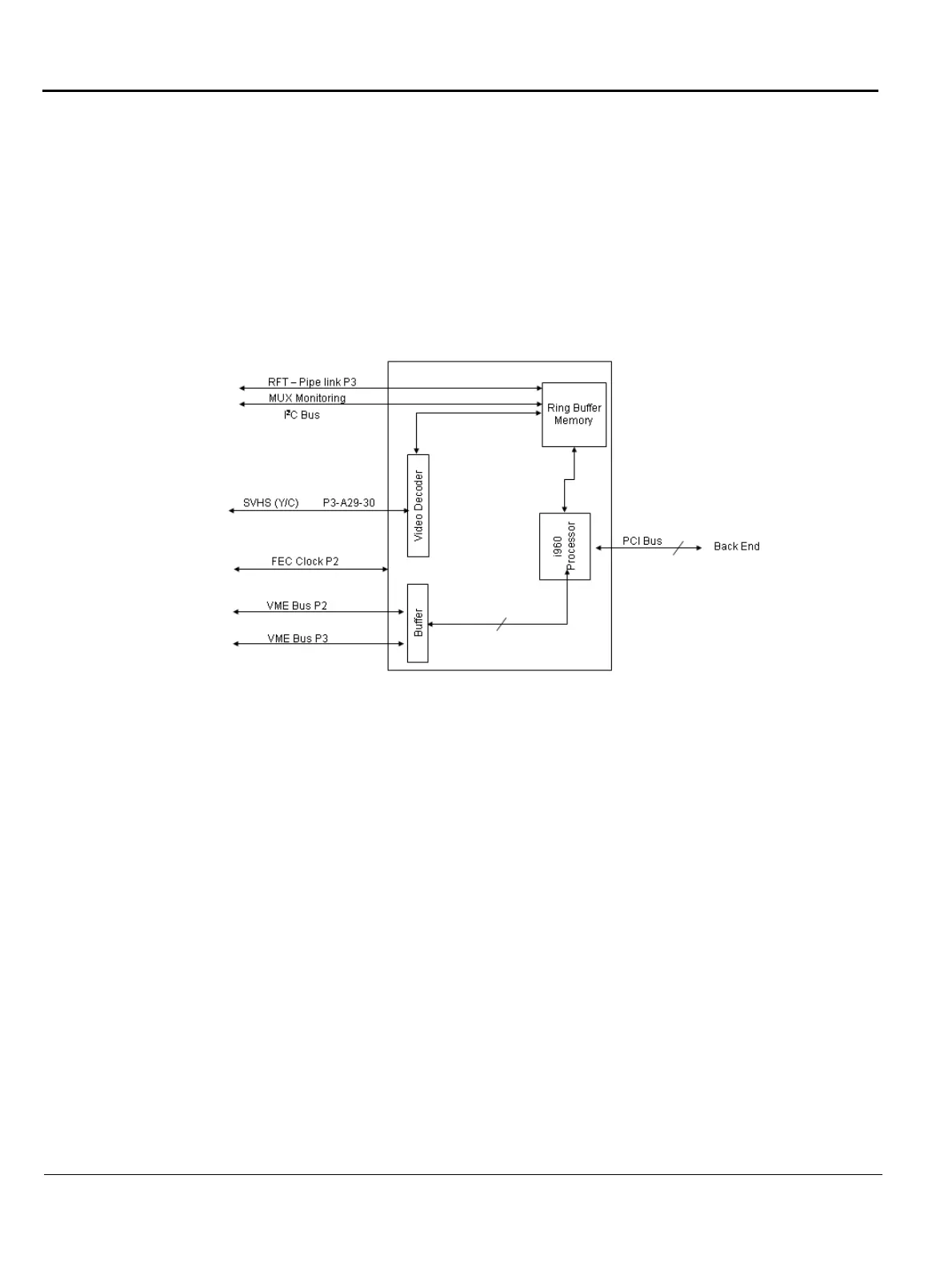
The function of the Image Port (IMP) is to receive signals from either the RFT (during scanning) or the
VCR (during playback), capture them, and route them to the Back End Processor (BEP) via the PC2IP
Bus. The IMP handles all the communication from the BEP to the Front End Cards and back through
the VME Bus - see Figure 5-14 below.
The IMP is used as a connection to the BEP. All the instructions to the Front End Crate are sent via the
IMP, and all the outgoing data is transferred to the BEP via the IMP through the PCI Bus.
5-4-11 Radio Frequency Interface Board (RFI)
The RFI board replaces the FEC, the RFT and the IMP boards.
NOTE: The SVHS (Y/C) signals are connected to the Frame Grabber card in the BEP on units with RFI.
5-4-12 Back Plane Board (Motherboard)
The Back Plane Board serves as a mother board which connects all the boards’ signals. It also
distributes the low voltages for the FE Crate boards and the TX voltages. It hosts all the FE boards, as
shown in Figure 5-1 on page 5-4.
NOTE: The Back Plane Boards are different between units with RFT and RFI.
Figure 5-14
Image Port Block Diagram
Front End Back End
Image Port
(IMP)