GE MEDICAL SYSTEMS
D
IRECTION FK091075, REVISION 04 VIVID 3N PRO/EXPERT SERVICE MANUAL
Chapter 3 Installation 3-29
3-6-4 Connecting the ECG
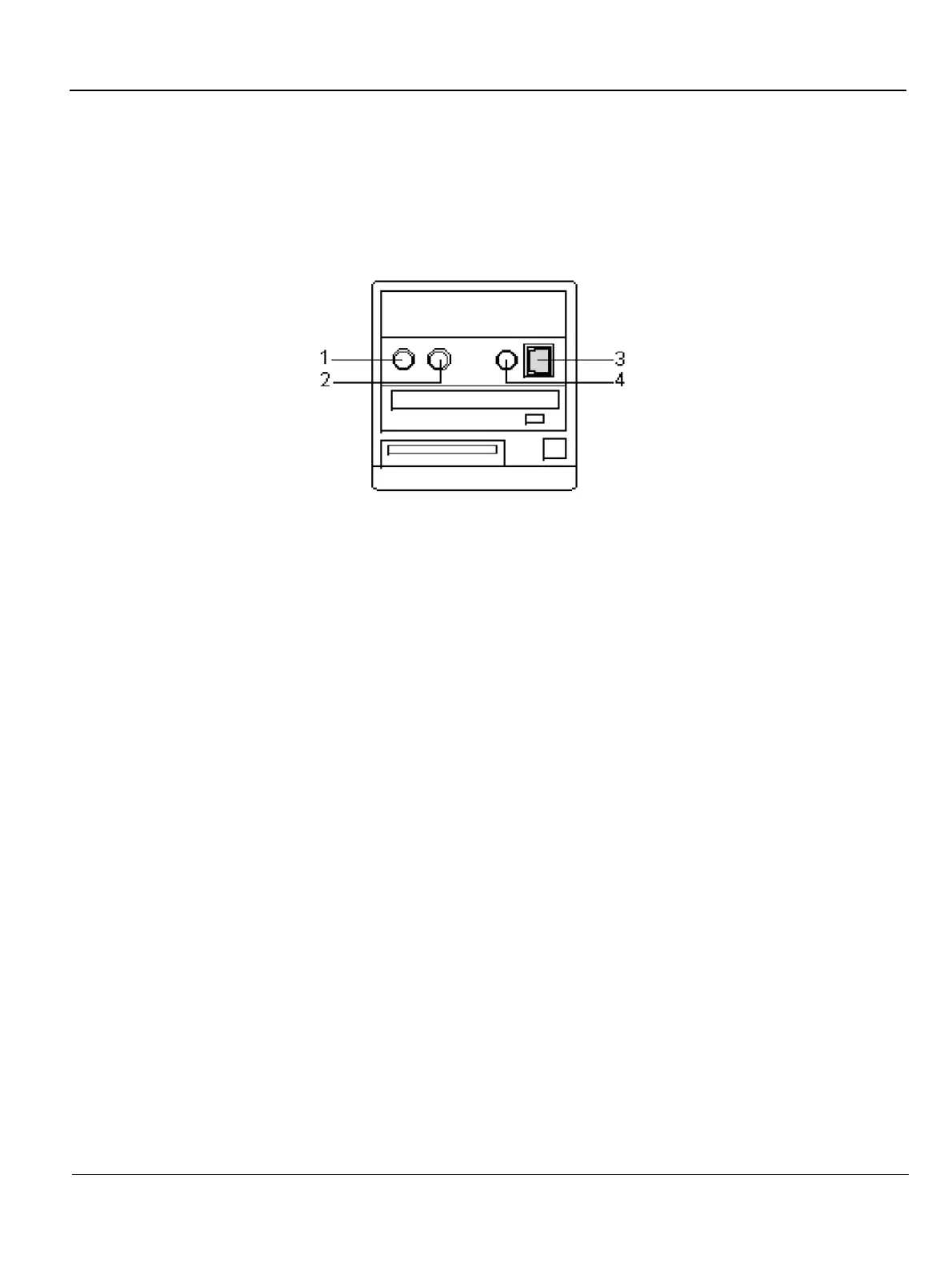
The internal ECG is connected into a rectangular-shaped socket on the patient trace (I/O) panel. The patient
trace (I/O) panel is located on the front of the ultrasound unit, as shown in Figure 3-7 "Front and Side View
of the Vivid 3N Pro/Expert" on page 3-14. Each socket is clearly labelled and color coded, as shown in
Figure 3-15 below.
1 Footswitch (black)
2 Phono (blue)
3 ECG (green)
4 External ECG (yellow)
The ECG cable is a modular cable consisting of four different cable parts. The main part (trunk) is a
single cable connecting to the unit at one end, and providing a cable splitter device at the other end.
The splitter contains five receptacles, only three of which are used with the Vivid3N Pro/Expert
ultrasound unit.
Three color coded electrode cables are inserted into the splitter in the appropriate color-coded
receptacles. Each electrode cable hooks up to the appropriate stick-on electrode by a clip-type
connector. The color coding of the electrodes follows one of two standards that are common in different
parts of the world. The cable splitter has a drawing defining the color codes, names and electrode
placements for each of the three cables, as shown in Figure 3-16 "ECG Cable and Electrode
Placement" on page 3-30.
Figure 3-15 Connection Sockets for ECG Cables
 Loading...


