GE MEDICAL SYSTEMS
D
IRECTION FK091075, REVISION 04 VIVID 3N PRO/EXPERT SERVICE MANUAL
Chapter 5 Components and Function (Theory) 5-43
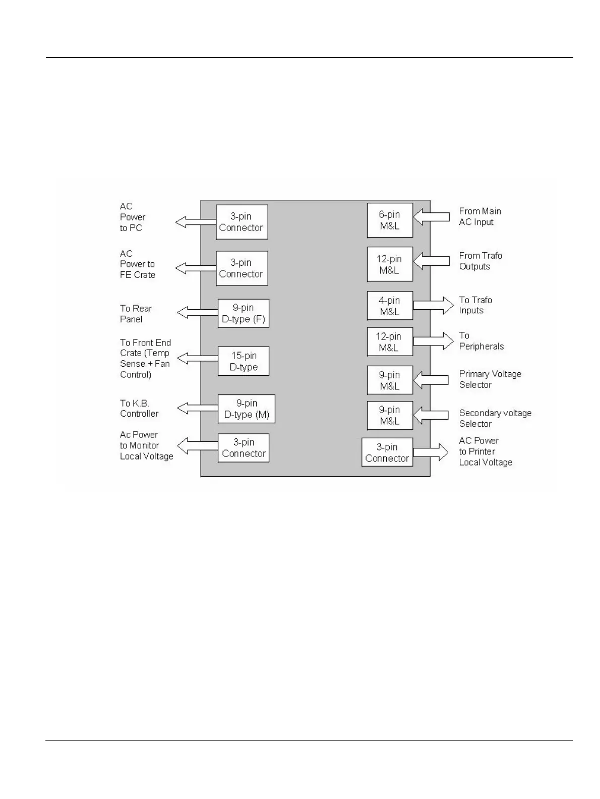
5-7-3 AC Distribution Box
The AC Distribution Box contains an electronic board that selects the proper Input and Output system
AC voltages, the load connectors, and the low voltage 12 V power supply. In addition, the AC
Distribution Box controls the soft AC Start Circuit, the temperature sensor and the Fan Control Circuit.
NOTE: The cable to the fans also carries a playback video signal from the VCR to the Image Port.
5-7-3-1 AC Input Box
The AC Voltage Input cord is connected to the AC Input Box. It contains the Dual Rating Circuit Breaker
6A - 200 - 240V or 12A 100 - 120V.
5-7-3-2 Thermal Fuses
The system has three internal AC thermal fuses. One is connected to the secondary coil of the
transformer, and supplies 230V to the system. The other two fuses are connected to the two coils that
supply the local voltages (100V,120V, 220V-230V or 230V-240V). The coils are connected in parallel
to the local voltage configuration.
The thermal fuses are located on the left rear panel.
Figure 5-27 AC Distribution Box Connectors Block Diagram
230 V
230 V
230 V
230 V
 Loading...


