GE MEDICAL SYSTEMS
D
IRECTION FK091075, REVISION 04 VIVID 3N PRO/EXPERT SERVICE MANUAL
8-26 Section 8-2 - Cover Replacement Procedures
8-2-14 Rear Handle Replacement Procedure
NOTE: This procedure describes the replacement procedure for the Vivid 3N Rear Handle (P/N
225392-5)
8-2-14-1 Tools
Use the appropriate Phillips-type screw drivers and a combination wrench, as described in the
procedures below.
8-2-14-2 Preparation
Shut down the Vivid 3N ultrasound unit, as described in Chapter 3 - Installation
8-2-14-3 Rear Handle Removal Procedure
1.) Carefully remove the monitor, as described in the Vivid™ 3 Monitor 15" Removal Procedure on
page 8 - 28 or the Vivid 3 17" Monitor Removal - Procedure 1 on page 8 - 30 (as appropriate).
2.) Remove the control console lower cover, as described in the Control Console Bottom Cover (Upper
Section) Removal Procedure on page 8 - 17.
3.) Remove the six screws from the metal service cover on the base assembly and remove the cover.
4.) Push the VGA connector slightly to allow the control console bottom cover (lower section) to slide
down sufficiently to expose the rear handle securing screws (see Figure 8-27 below).
5.) Using a combination wrench, loosen and remove the two hexagon-head screws (one on each side)
that secure the rear handle to the upper console cover, as shown in Figure 8-27.
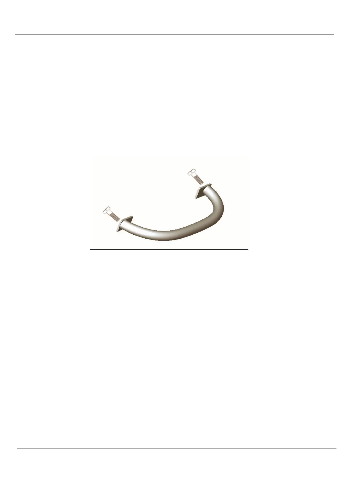
6.) Remove the Rear Handle.
Figure 8-26 Vivid 3 Rear Handle
 Loading...


