GE MEDICAL SYSTEMS
D
IRECTION FK091075, REVISION 04 VIVID 3N PRO/EXPERT SERVICE MANUAL
Chapter 8 Replacement Procedures 8-47
8-4-2 TR4 Boards Replacement Procedure
NOTE: The procedure below provides the instructions for replacing any of the TR4 boards ( P/N 2253036).
8-4-2-1 Tools
Use the appropriate flat and Phillips-type screw drivers and an ESD wrist band strap as indicated in the
TR4 Boards replacement procedure.
8-4-2-2 Preparation
1.) Shut down the Vivid™ 3 ultrasound unit, as described in Chapter 3 - Installation.
8-4-2-3 TR4 Boards Removal Procedure
1.) Remove the FE Board, as described in the Front End Boards Removal Procedure on page 8 - 44.
2.) Place the FE Board on a desk or a stable surface, on top of an ESD mat.
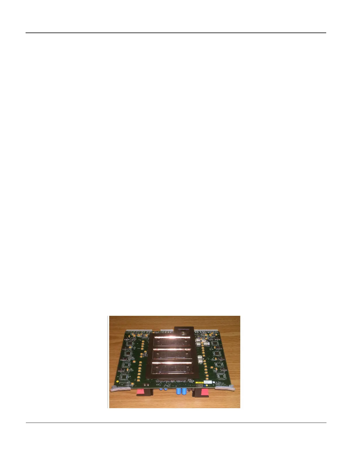
3.) Remove each of the four screws (two from each side) that hold the two brackets that secure the
TR4 boards to the FE Board main plate, as shown in Figure 8-43 below.
CAUTION
DO NOT TOUCH ANY BOARDS WITH INTEGRATED CIRCUITS PRIOR TO TAKING THE
NECESSARY ESD PRECAUTIONS:
CAUTION
1.ALWAYS CONNECT YOURSELF, VIA AN ARM-WRIST STRAP, TO THE ADVISED ESD
CONNECTION POINT LOCATED ON THE REAR OF THE SCANNER (TO THE RIGHT OF THE
POWER CONNECTOR).
2.FOLLOW GENERAL GUIDELINES FOR HANDLING OF ELECTROSTATIC SENSITIVE
EQUIPMENT.
CAUTION
FRONT END BOARDS ARE HEAVY!
WARNING
FAILURE TO TAKE PRECAUTIONS WHEN LIFTING , COULD RESULT IN PER-
SONAL INJURY AND/ OR DAMAGE TO THE SYSTEM.
Figure 8-45 Location of Screws on Securing Brackets
 Loading...


