GE MEDICAL SYSTEMS
D
IRECTION FK091075, REVISION 04 VIVID 3N PRO/EXPERT SERVICE MANUAL
8-46 Section 8-4 - Front End Parts Replacement
8-4-1-3 Front End Boards Removal Procedure (cont’d)
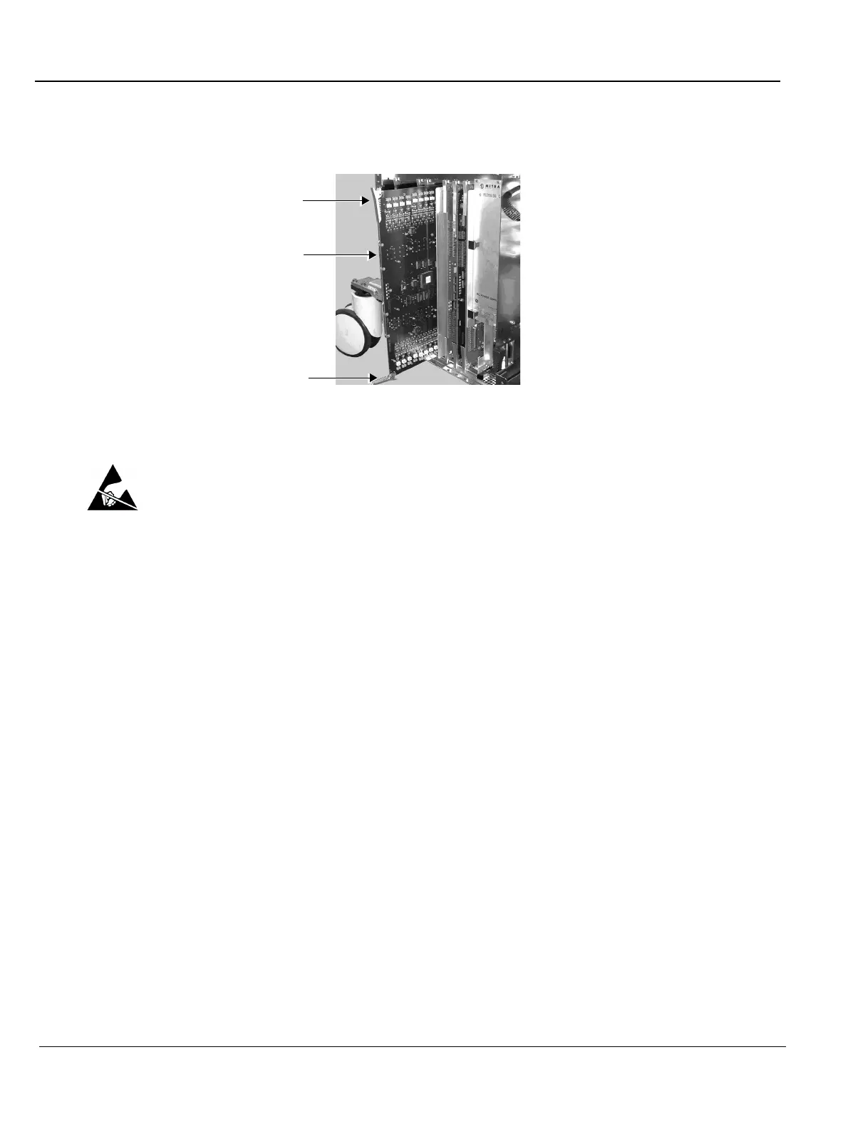
3) Release the plastic latches located at the top and the bottom of each card (board) - see Figure 8-44.
4) Gently pull the required card from the crate.
CAUTION: When removing the card, ESD may cause damage to the card. Always have the ESD hand
strip connected to the machine chassis and to your hand.
8-4-1-4 Front End Boards Installation Procedure
1) Gently slide and push the required card to its original location, using the metal frame guiding tracks.
2) Use the plastic latches to firmly lock in the card in position, so that the connectors are firmly placed
in their sockets.
3) Return the front door of the crate to its original position and tighten the two screws that secure the
door in place.
4) Return the left side cover to its original position, as described in 8-2-2-4 "Side Covers Installation
Procedure" on page 8-4.
NOTE: When you insert a Front End Board into the crate, ensure that the probe connector's
metal frame slides into its tracks.
NOTE: The Beamformer Calibration procedure must be performed each time a Beamformer is
replaced. Refer to the instructions in 6-8-3 "Beamformer Calibration" on page 6-24
Figure 8-44 Front End Boards
Upper latch
Lower latch
FE Board
 Loading...


