GE MEDICAL SYSTEMS
D
IRECTION FK091075, REVISION 04 VIVID 3N PRO/EXPERT SERVICE MANUAL
8-36 Section 8-3 - Control Console Components Replacement
8-3-3-3 Vivid 3N 17" Monitor Removal - Procedure 2 (cont’d)
Figure 8-37 Vivid 3N Monitor showing Underside
6) Remove the three screws that fasten the bracket at the front of the monitor, and then remove the
bracket.
7) Remove the screw located on the left of the VGA cable at the back of the monitor.
8) Remove the two remaining screws from the back of the monitor. This will release the space bar
located between the back of the monitor and the monitor base assembly.
9) Remove the two screws securing the base assembly to the monitor, located one on either side of
the bottom front of the monitor.
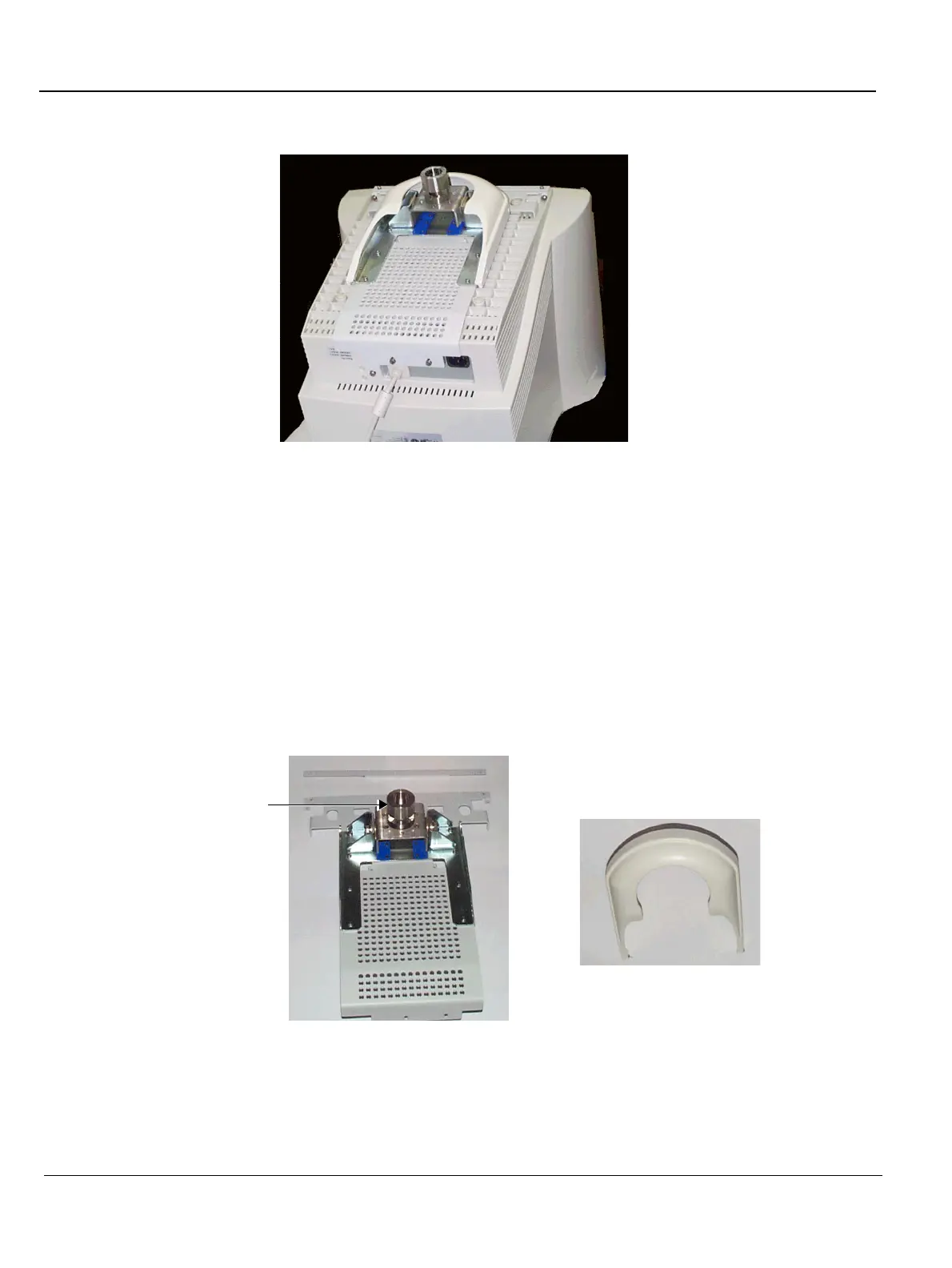
10) Push the base assembly towards the rear of the monitor until its hinges are released from the
monitor's case to release the base assembly, which can then be removed, as shown below:
Figure 8-38 Vivid 3N Base Assembly and Cover
Base Assembly
Cover
Pivot shaft
 Loading...


