EasyManua.ls Logo

Honeywell VOYAGER 1202G BF User Manual

Honeywell VOYAGER 1202G BF
230 pages
To Next Page IconTo Next Page
To Previous Page IconTo Previous Page
Page #71 background imageLoading...
Page #71 background image
4 - 1
4
Cordless System Operation (Voyager 1202g-BF)
Note: This chapter applies only to Voyager 1202g-BF cordless scanning systems (PN: 1202G-BF). It does not apply to corded
or Voyager 1202g scanners. See Cordless System Operation (Voyager 1202g) on page 3-1 for Voyager 1202g scanners.
How the Charge and Communications Base Works
A charge and communications base provides the link between the cordless scanner and the host system. The base contains an
interface assembly and an RF communication module. The RF communication module performs the data exchange between
the cordless scanner and the interface assembly. The control assembly coordinates the central interface activities including:
transmitting/receiving commands and data to/from the host system, performing software activities (parameter menuing, visual
indicator support, power-on diagnostics), and data translation required for the host system.
The base is also the scanner’s instant charge pack charger. Refer to Charging Information, page 4-3, for additional information.
Linking the Scanner to a Base
When the base is connected and powered up, put the scanner in the base to establish a link. The red LED on the base lights to
indicate power, and the green LED flashes to indicate the scanner’s instant charge pack is charging.
Note: The scanner’s instant charge pack must be charged to establish a link with the base.
The scanner emits a two tone beep sequence when the scanner and base radios link. That indicates the scanner is linked to
the base.
To determine if your scanner has linked to the base correctly, scan one of the sample bar codes in the back of this manual. If the
scanner provides a single good read beep and the green LED lights, the scanner has successfully linked to the base. If you
receive an error chirp when the scanner’s button is pressed and the bar code is not scanned, the scanner has not linked to the
base.
Note: If the powered interface cable is unplugged from the base, the scanner will unlink. The scanner will relink once the
powered interface cable is connected.
Communication Between the Cordless System
and the Host
The cordless scanner provides immediate feedback in the form of a “good read” indication (a red LED will turn into a green LED
on the scanner and an audible beep) after a bar code is scanned correctly and the base has acknowledged receiving the data.
This is possible since the cordless system provides two-way communication between the scanner and the base.
Scanner
Base
Base LEDs
Page Button

Table of Contents

Other manuals for Honeywell VOYAGER 1202G BF

Question and Answer IconNeed help?

Do you have a question about the Honeywell VOYAGER 1202G BF and is the answer not in the manual?
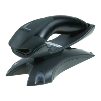
Honeywell VOYAGER 1202G BF Specifications

General IconGeneral
Product NameHoneywell VOYAGER 1202G BF
CategoryBarcode Reader
Scanner TypeLaser
Battery-Free TechnologyYes
Scan Rate100 scans per second
Decode Capability1D Barcodes
InterfaceUSB, Keyboard Wedge, RS232, IBM 46xx (RS485)
Operating Temperature0°C to 50°C (32°F to 122°F)
Storage Temperature-40°C to 70°C (-40°F to 158°F)
Weight180g (6.3 oz)
Dimensions180 mm x 66 mm x 92 mm (7.1 in x 2.6 in x 3.6 in)
ConnectivityBluetooth
Radio RangeUp to 10 meters
Scan PatternSingle Line
Humidity5% to 95% relative humidity, non-condensing
Drop SpecificationWithstands 30 drops to concrete from 1.5 m (5 ft)
Power SourceBattery-Free with Supercapacitor
Resolution1D: 4 mil (0.102 mm), 2D: 6.7 mil (0.169mm)

Summary

Chapter 1 - Getting Started

Connecting the Device

Instructions for physically connecting the scanner to a host system.

Connecting with USB

Steps for establishing a connection using a USB interface.

Connecting with Keyboard Wedge

Steps for connecting the scanner via a keyboard wedge interface.

Connecting with RS232 Serial Port

Steps for connecting the scanner using an RS232 serial port.

Chapter 2 - Programming the Interface

Keyboard Wedge

Configuring the scanner for keyboard wedge emulation.

RS232 Serial Port

Configuring the scanner for RS232 serial communication.

USB PC or Macintosh Keyboard

Setting up the scanner for USB PC or Mac keyboard emulation.

Chapter 3 - Cordless System Operation (Voyager 1202g)

Linking the Scanner to a Base

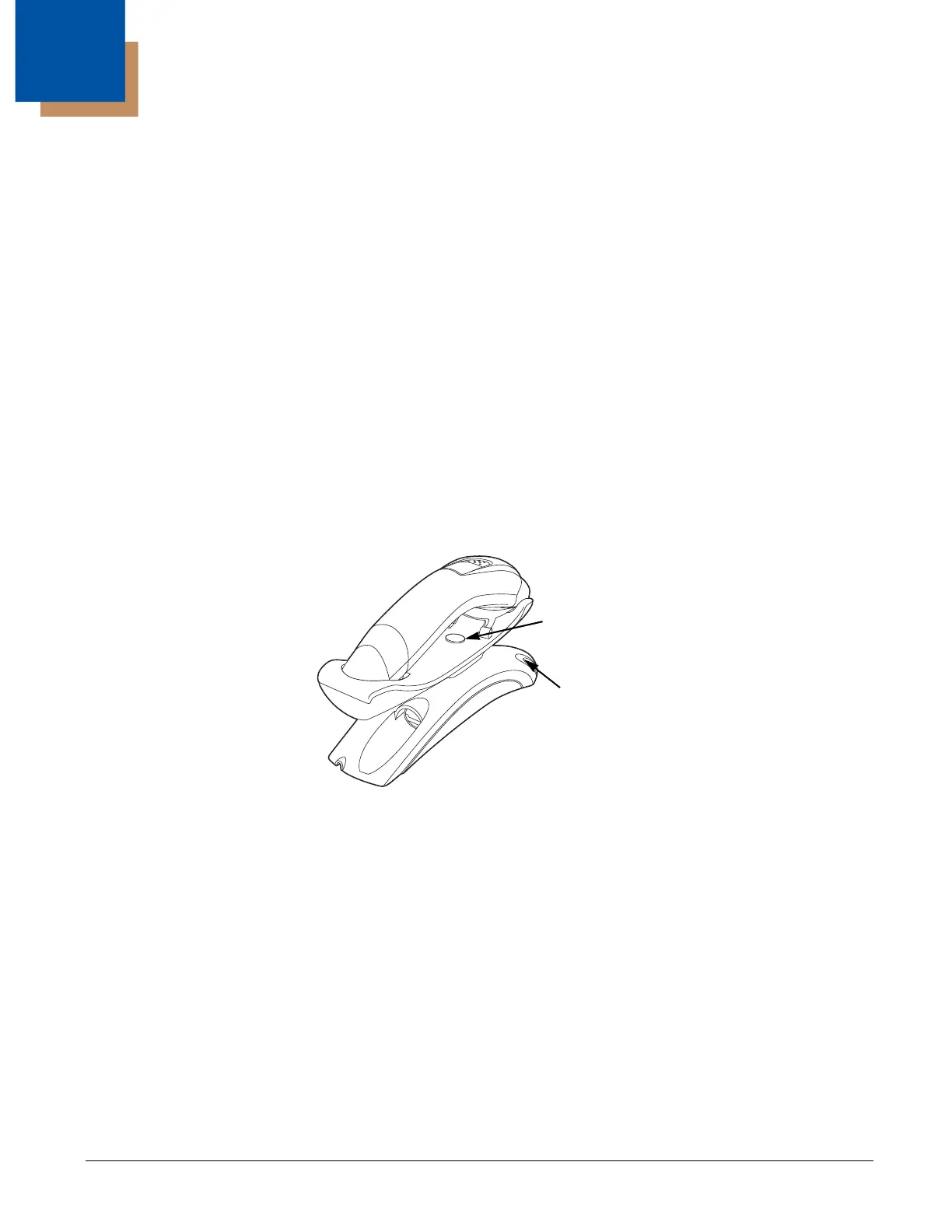
Step-by-step guide to establishing a wireless link between scanner and base.

Chapter 8 - Symbologies

Chapter 13 - Maintenance and Troubleshooting

Troubleshooting a Voyager Scanner

Common issues and solutions for scanner operation problems.

Troubleshooting a Cordless System

Common issues and solutions for cordless system operation.

Related product manuals